Saia-Burgess Controls AG
Manual Manual PCD 1 / PCD 2 Series │ Document 26 / 737 EN22 │ 2013-11-26
5
Input/output (I/O) modules
5-80
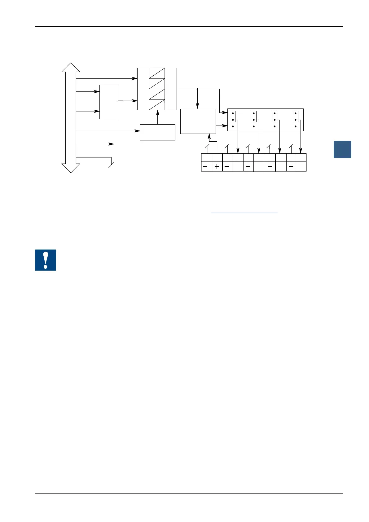
Analogue output modules
Block diagram
D
A
D
A
D
A
D
A
2
3
V
C
9 8 7 6 5 4 3 2 1 0
A0 A1 A2 A3
V
C
0
1
I/O Bus
PCD Bus
Reference
Voltage
DATA
WRITE
ADDR
JUMPER J2
24 V
DC
VOLTAGE
CONTROLLED
CURRENT
SOURCE
Programming
Classic: Programming examples for the PCD2.W4x0 can be found in a separate
manual and on the TCS Support site (www.sbc-support.com + getting
started).
xx7: the rmware writes the values according to the conguration (I/O Builder)
Watchdog: This module cannot be used on the base address 240 (or 496 for the
PCD2.M17x), because it would interact with the watchdog, and would cause a
malfunction.
For details, please refer to the “Watchdog” section, which describes the correct use of
the watchdog in conjunction with PCD2 components.