Saia-Burgess Controls AG
Manual Manual PCD 1 / PCD 2 Series │ Document 26 / 737 EN22 │ 2013-11-26
CPUs and expansion housings
3-44
Expansion of user memory
3
The following chips will work, but are no longer recommended for new installations:
Memory type Item-no. Typical codes Size
RAM 4 502 5414 0
1)
SRM2B256LCX70
HY62256ALP-70
GM76C256CLL-70
MELM5M5256DP-70LL
TC55257DPL-70L
256 Kbits / 32 Kbytes
EPROM
2)
450239580 AM27C512-90DC
UPD27C512D-10
M27C512-10XF1
M27C512-10F1
512 Kbits / 64 Kbytes
Steps in the correct installation of extended user memory:
1) Switch off power supply and remove the cover of the PCD2
2)Plugtheadditionalmemorychipintothe“USERPROG”socket.
Ensure correct alignment (markings on the socket and the chip must match), and
ensure that all pins on the chip are inserted into the socket
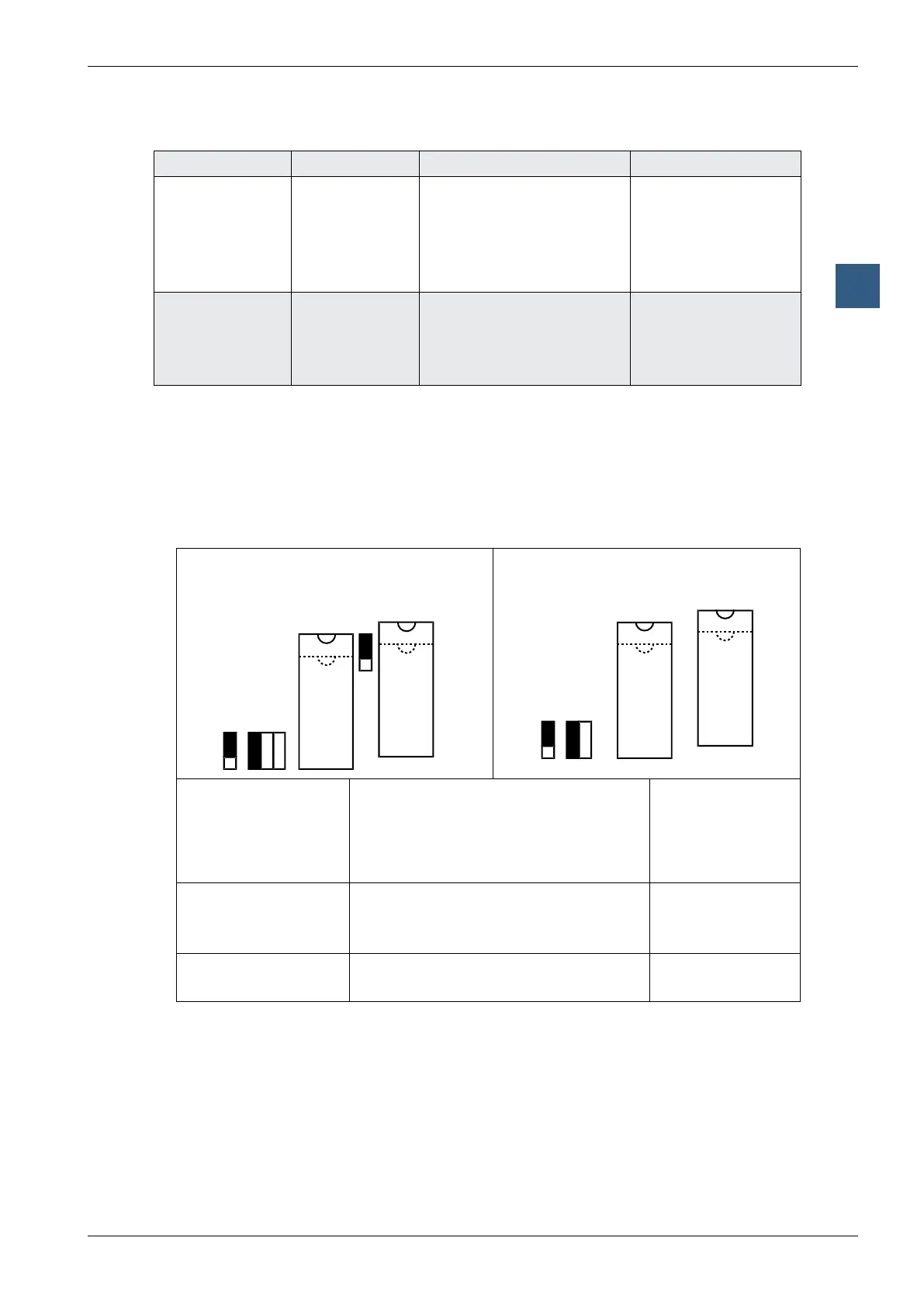
3) Set the jumper next to the socket correctly:
PCD2.M110/M120 hardware version ≥ H
and PCD2.M150
USER PROG
PCD2.M110/M120 hardware version < H
Firmware
R E
J3
J2
WP
USER PROG
Jumper
J1 (memory type) RAM
EPROM
Flash EPROM
Position
R
1)
E
F
2)
J3 (write-protection) Writeprotectiondeactivated
3)
Writeprotectionactivated
3)
(only works
for RAM and Flash EPROM)
up
1)
WP(down)
J5 (memory size <= 1
Mbit or > 1 Mbit)
2)
Memory size <= 1 Mbit
Memory size > 1 Mbit
up
1)
down
1) Jumperpositionondelivery:RAM,write-protectiondeactivated,memorysize≤1Mbit
2) OnthePCD2.M110/M120withhardwareversion<H,J5andtheJ2Fjumperarenotpresent.Thismeans
that where Flash EPROM is used with these controllers, J2 has to be attached to E and only chips up to 1
Mbit can be used for expansion
3) Write-protectiononlyaffectsthechipintheUSERPROGsocket
4) ModifythehardwareconfigurationinPG5accordingly,anddownloadthenewconfiguration