Section 11 ELECTRICAL CONNECTORS AND WIRING DIAGRAMS
Subsection 01 (ELECTRICAL CONNECTORS)
F00H0QA
1
2
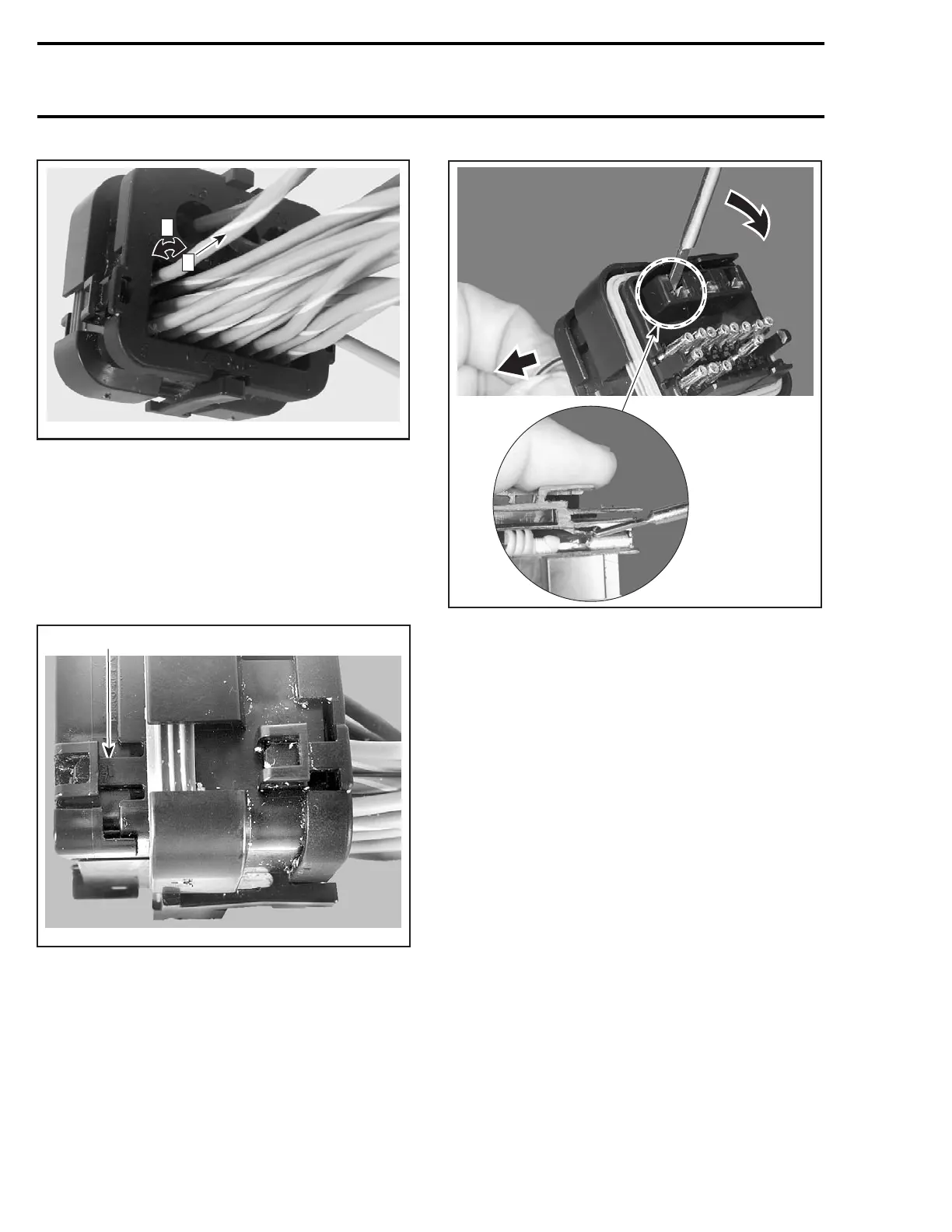
Step 1: Rotate wire back and forth
Step 2: Pull wire
POWER WIRE TERMINAL
NOTE: The wedge lock must be removed to ex-
tract power terminal.
Open the wedge lock.
Pull both locking tabs and remove wedge lock
from connector.
F00H0RA
1
1. Pull locking tab (both sides)
Before extraction, push wire forward to relieve
pressure on retaining tab.
Insert a 4.8 mm (.189 in) wide screwdriver blade
inside the front of the terminal cavity.
F00H0ZA
Pry back the retaining tab while gently pulling wire
back until terminal is removed.
Terminal Crimping
Thesizeofthewiresmustbe20to16AWGwith
a wire insulation diameter having a minimum di-
mension of 1.7 mm (.067 in) and a maximum di-
mensionof2.78mm(.106in).
The wire strip length must be 5.1 mm (13/64 in).
NOTE: When stripping wires, ensure conductor is
not nicked, scrapped or cut. Wire stripping tool
jaws may leave marks on the surface of the wire
insulation. If these marks occur at the location
of the wire seal, leakage may result. Insulation
surface within 25 mm (1 in) from the tip of the
terminal must be smooth.
All terminals in AMP connectors must be crimped
using the crimping tool (P/N 529 035 909) and
crimper die (P/N 529 035 908).
300 smr2005-026
 Loading...


