MRD 3187B - User Manual
Page 90 (245)
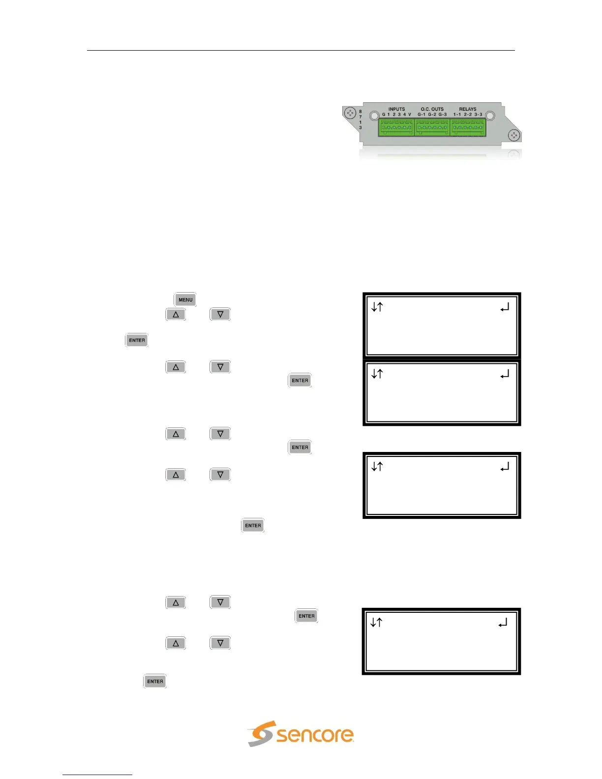
4.13 GPIO Module – 8713
General Information
Install Location: Any slot except 1-1 or 2-1.
I/O: Logic Input, Open-Collector, and Relay
Contact
Description: This module is considered a global unit option. The inputs and outputs
of a single installed module can be accessed by functions associated with
general system features, or RDS specific features in any unit configuration. Only
one GPIO module can be installed in a unit.
DTMF Tones
To setup the MRD 3187B to interpret a contact closure from a receiver (getting
DTMF analog cue tones) and output an embedded SCTE104 message in the SDI
output, use the following steps:
1. Press the button.
2. Use the and buttons to move the
cursor to “GPIO Module”, then press the
button.
3. Use the and buttons to move the
cursor to “Input 1”, then press the
button.
4. Use the and buttons to move the
cursor to “Input 1”, then press the
button.
5. Use the and buttons to select
the message (“SCTE104 RDS1 1”,
“SCTE104 RDS1 2”, “SCTE104 RDS1 3”,
“SCTE104 RDS1 4”) that is to be
inserted, then press the button to
save the selection.
Ex: SCTE104 RDS1 1 refers to splice request 1 that will be output on RDS1. In units
with RDS2, the message options of “SCTE104 RDS2 1”, “SCTE104 RDS2 2”,
“SCTE104 RDS2 3”, “SCTE104 RDS2 4” are also available.
6. Use the and buttons to move the
cursor to “Active State”, then press
button.
7. Use the and buttons to select
the state (“High” or “Low”) in which the
input will be considered active, then press
the button to save the selection.
GPIO Module 2-4 1
Input 1:SCTE104 RDS1
►Active State:High
GPIO Input 2-4 1
►Input:SCTE104 RDS1 1
Active State:High
GPIO Module 2-4
►Input 1:None
Input 2:None
Input 3:None
Menu
Event Log
►GPIO Module
Splice Requests