MRD 3187B - User Manual
Page 91 (245)
Note: The aforementioned steps apply to the configuration of “Inputs 1-4, Outputs
1-3, and Relays 1-3” as well.
Splice Request Setup
Once the Input is setup the outgoing SCTE104 messages need to be configured.
Use the following steps to configure the outgoing SCTE104 messages:
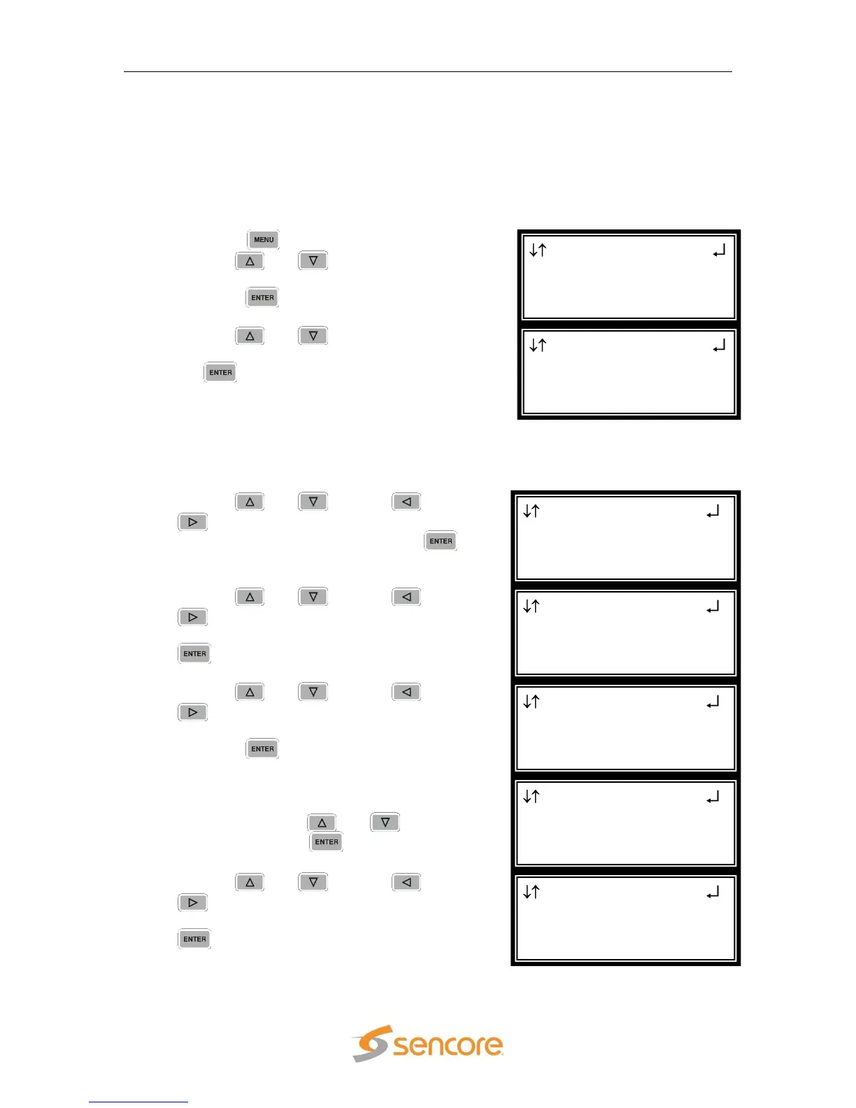
1. Press the button.
2. Use the and buttons to move the
cursor to “Splice Requests”, and then
press the button.
3. Use the and buttons to move the
cursor to “Splice Req 1”, and then press
the button.
Note: The following steps apply to Splice Req 1 – 4.
Note: The number “1-1” in the header “Splice Req 1-1” refers to the RDS and the
Splice Request 1. The second Splice request will be numbered “1-2”.
1. Use the and , and the and
buttons to set the “AS Index:” to the
desired amount, and then press the
button.
2. Use the and , and the and
buttons to set the “DPI PID Index:” to
the desired amount, and then press the
button.
3. Use the and , and the and
buttons to set the “Event Source
Index:” to the desired amount, and then
press the button.
4. For the “Splice Type:” choose (“OON”,
“OON Imm”, “RTN”, “RTN Imm”, or
“Cancel) using the and buttons,
and then press the button.
5. Use the and , and the and
buttons to set the “Program ID:” to
the desired amount, and then press the
button.
Splice Req 1-1
Splice Type:OON
►Program ID:0x0000
Preroll:04000
Splice Req 1-1
►Splice Type:OON
Program ID:0x0000
Preroll:04000
Splice Req 1-1
AS Index:000
DPI PID Index:00000
►Event Source:0x0
Splice Req 1-1
AS Index:000
►DPI PID Index:00000
Event Source:0x0
Splice Req 1-1
►AS Index:000
DPI PID Index:00000
Event Source:0x0
Splice Requests 1
►Splice Req 1
Splice Req 2
Splice Req 3
Menu
Event Log
GPIO Module
►Splice Requests