Operat ion CDHD
188 User Manual
GEARMODE 1 if connected through the Controller I / F connect or (C2)
GEARMODE 4 if connected through the Machine I/ F connector (C3).
Pulse and Direct ion Com m ands Using a Single - Ended Sign al
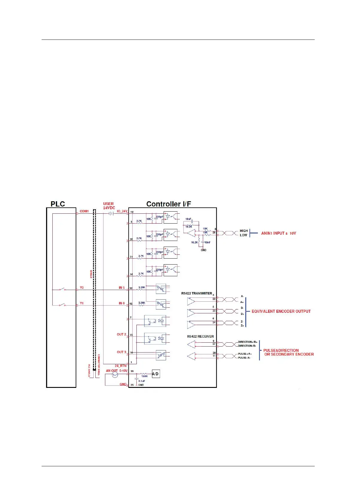
The CDHD enables the connection of PLCs with a 24 VDC single-end signal to the
drive. This type of signaling requires the use of the fast digital inputs on the
CDHD Controller I/ F connector (C2) .
The Pulse signal is connected to fast digital input 5 on pin 32.
The Direction signal is connected to fast digital input 6 on pin 15.
Refer to Figure 8-6 below. The diagram shows how t o connect the PLC t o the
CDHD Controller I/ F (C2) connect or.
Connect the cable shield on the PLC side to any available shield connector.
Connect the cable shield on the CDHD side to the shell of the 36-pin
connect or.
N ot es: The 24 VDC power supply must be provided by the user.
Refer also to Table 3-10. I / O Specifications.
Figur e 8 - 6 . W iring for Pulse and Direct ion Using Single- Ende d Signal
Pulse and Direct ion Opera tion
For Pulse and Direction operation, the sett ings in the ServoStudio M o t ion screen
are similar to those shown in the following figure. Actual values may differ. Refer
to this figure when perform ing t he following st eps.