CDHD Drive Setup
User Manual 89
W ir in g – Single - Ende d H alls
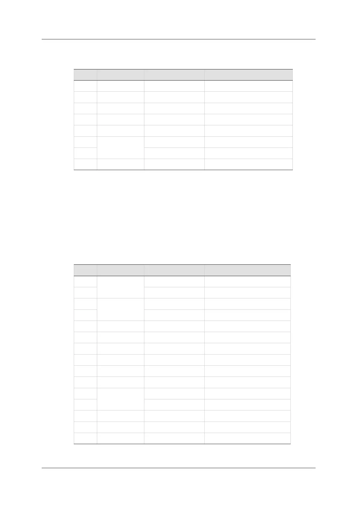
Ta ble 5 - 1 3 . Fe edba ck W iring – Sin gle - En ded Halls
Pin # Tw ist ed Pair User Motor Pin# Sign a l De scr ipt ion
4 Hall U
17 Hall V
5 Hall W
11 + 5 VDC
24 0 VDC
12
Twisted Pair
Motor Temperature Sensor
25 Mot or Temperature Sensor
26 Shield
N ot es: I f t he m otor does not support a t em perature sensor, do not connect
pins 12 and 25.
Halls are single-ended signals. I f you want to use differential Hall
signals, refer to the relevant wiring tables.
W ir in g – I ncrem e ntal Encoder A Qua d B, I ndex Pulse and Differ ent ial
Ha lls
Ta ble 5 - 1 4 . Fe edba ck W iring – I ncrem e n t a l Encoder A Quad B, I ndex
Pulse and D if fer en t ial Ha lls
Pin # Tw ist ed Pair User Motor Pin# Sign a l De scr ipt ion
1
Twisted Pair
I ncrem ent al Encoder A+
14 I ncrem ent al Encoder A-
2
Twisted Pair
I ncrem ent al Encoder B+
15 I ncrem ent al Encoder B-
9 Hall U+
22 Hall U-
10 Hall V+
23 Hall V-
3 Hall W+
16 Hall W-
12
Twisted Pair
Motor Temperature Sensor
25 Mot or Temperature Sensor
11 + 5 VDC
24 0 VDC
26 Shield
N ot es: I f t he m ot or does not support a tem perature sensor, do not connect
pins 12 and 25.
 Loading...

