Drive Setup CDHD
90 User Manual
To use differential Halls with A quad B and index, connect the Halls to
the Machine int erface as follows:
Hall U+ t o Machine I / F pin 1, Hall U- t o Machine I / F pin 11.
Hall V+ to Machine I / F pin 2, Hall V- to Machine I / F pin 12.
Hall W+ to Machine I / F pin 3, Hall W- to Machine I / F pin 13.
Connect the encoder A, B, I, and power supply to the Mot or Feedback
connect or.
On every power up, phase find ( PHASEFI ND) must be executed.
W ir in g – Diffe rential Halls On ly
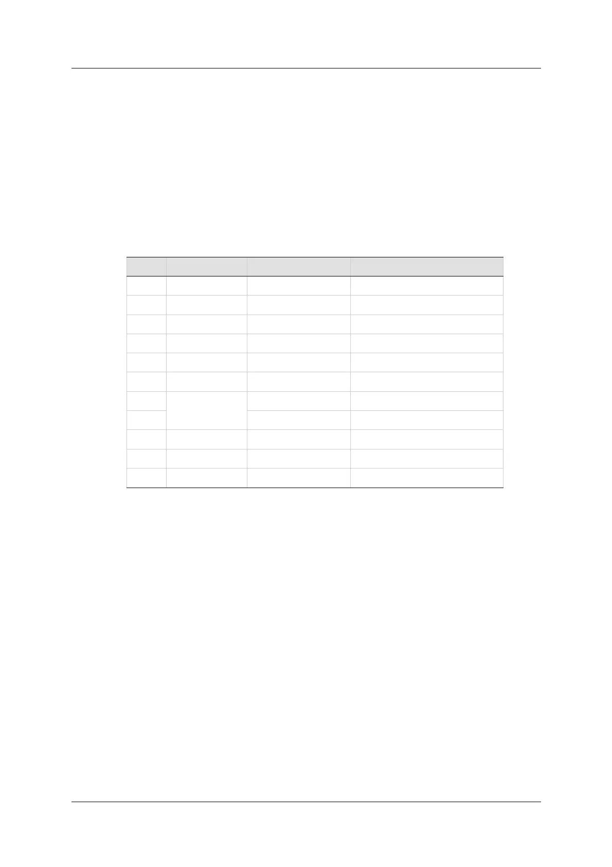
Ta ble 5 - 1 5 . Fe edba ck W iring – Differen t ial Ha lls On ly
Pin # Tw ist ed Pair User Motor Pin# Sign a l De scr ipt ion
9 Hall U+
22 Hall U-
10 Hall V+
23 Hall V-
3 Hall W+
16 Hall W-
12
Twisted Pair
Motor Temperature Sensor
25 Mot or Temperature Sensor
11 + 5 VDC
24 0 VDC
26 Shield
N ot es: I f t he m ot or does not support a tem perature sensor, do not connect
pins 12 and 25.
 Loading...

