Drive Setup CDHD
94 User Manual
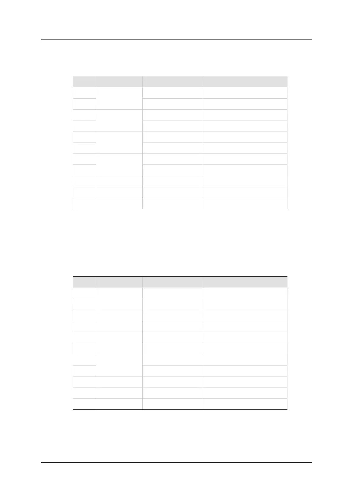
W ir in g – Sick 5 V ( H I PERFACE Protocol and Sine Signal)
Ta ble 5 - 2 1 . Fe edba ck W iring – Sick 5 V ( HI PERFACE Prot ocol a nd Sine
Sign a l)
Pin # Tw ist ed Pair User Motor Pin# Sign a l De scr ipt ion
1
Twisted Pair
Serial Dat a +
14 Serial Dat a -
9
Twisted Pair
Sine Encoder Sine+
22 Sine Encoder Sine-
10
Twisted Pair
Sine Encoder Cosine+
23 Sine Encoder Cosine-
12
Twisted Pair
Motor Temperature Sensor
25 Mot or Temperature Sensor
11 + 5 VDC
24 0 VDC
26 Shield
N ote: I f the m ot or does not support a temperature sensor, do not connect
pins 12 and 25.
W ir in g – Sick 8 V ( H I PERFACE Protocol and Sine Signa l)
Ta ble 5 - 2 2 . Fe edba ck W iring – Sick 8 V ( HI P ERFACE Prot ocol a nd Sine
Sign a l)
Pin # Tw ist ed Pair User Motor Pin# Sign a l De scr ipt ion
1
Twisted Pair
Serial Dat a +
14 Serial Dat a -
9
Twisted Pair
Sine Encoder Sine+
22 Sine Encoder Sine-
10
Twisted Pair
Sine Encoder Cosine+
23 Sine Encoder Cosine-
12
Twisted Pair
Motor Temperature Sensor
25 Mot or Temperature Sensor
18 + 8 VDC
24 0 VDC
26 Shield
N ote: I f t he m otor does not support a temperature sensor, do not connect
pins 12 and 25.
 Loading...

