105
8012428/YWL2/3-0/2016-08| SICK O P E R A T I N G I N S T R U C T I O N S | DUSTHUNTER T
Subject to change without notice
TROUBLESHOOTING 6
6Troubleshooting
6.1 General
Warning or error messages are output as follows:
● On the MCU, the respective relay is switched on (see “Standard connection”, page 53).
● “Maintenance requ.” or “Failure” is displayed in the status bar on the LC-Display of the
MCU (option for DUSTHUNTER T50) (). In addition, the respective LED goes on
(“MAINTENANCE REQUEST” for warnings, “FAILURE” for errors).
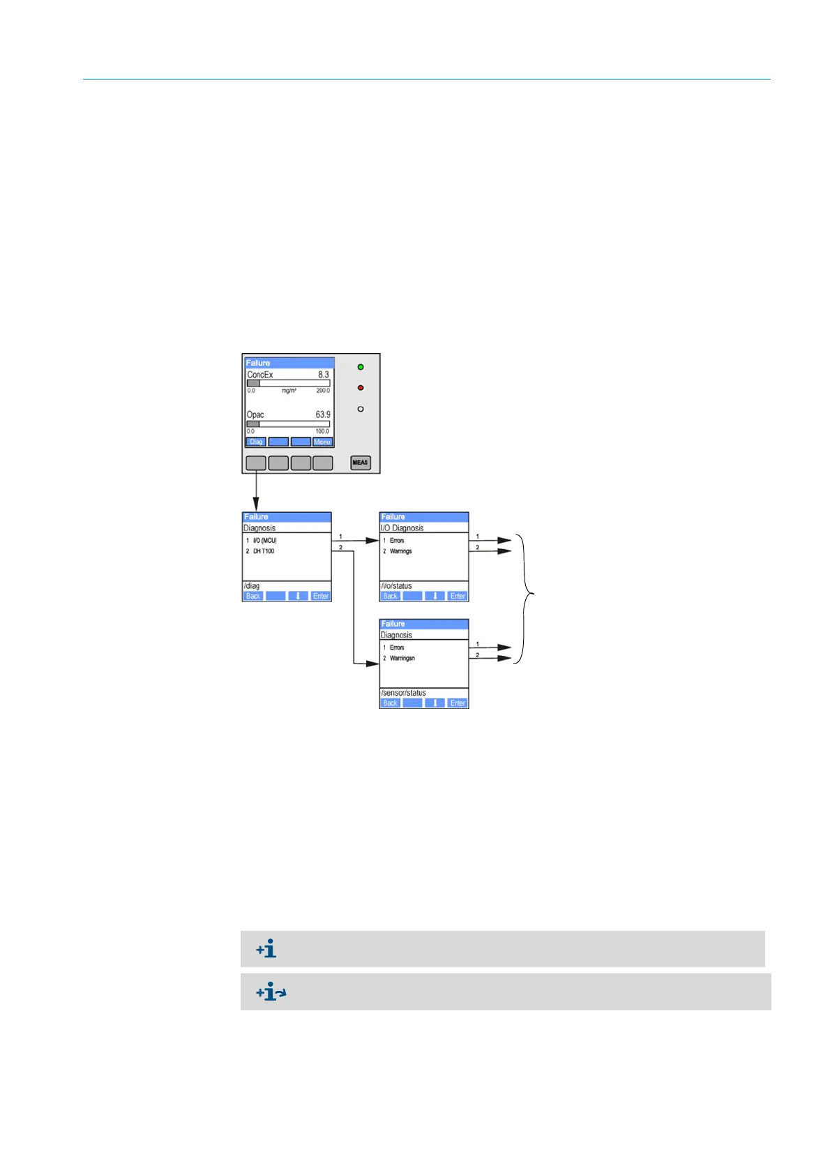
After pressing the button “Diag”, possible causes are shown as short information in the
menu “Diagnosis” after selecting the device (“MCU” or “DH T 50 / DH T100 / DH T200”).
Fig. 74: Display on the LC-Display
“Diagnosis / Error messages/warnings” provides detailed information on the current device
state. To display, connect the measuring system to SOPAS ET and load the device file “DH
T50 / DH T100 / DH T200” or “MCU” (see “Connection to the device via USB line”,
page 58).
Move the mouse to the respective message to display more details on the significance of
individual messages in a separate window. Clicking on the display shows a short descrip-
tion of possible causes and corrections under “Help” (see “Warning and error messages in
SOPAS ET”, page 106, ).
Warning messages are output when internal limits for individual device functions/
components are reached or exceeded which can then lead to erroneous measured values
or an imminent failure of the measuring system.
Display of current warning or failure
Warning messages do not imply a malfunction of the measuring system. The current
measured value continues to be output on the analog output.
See the Service Manual for a detailed description of messages and options for
clearance.
 Loading...


