33
8012428/YWL2/3-0/2016-08| SICK O P E R A T I N G I N S T R U C T I O N S | DUSTHUNTER T
Subject to change without notice
PRODUCT DESCRIPTION 2
2.3.2 Device configuration
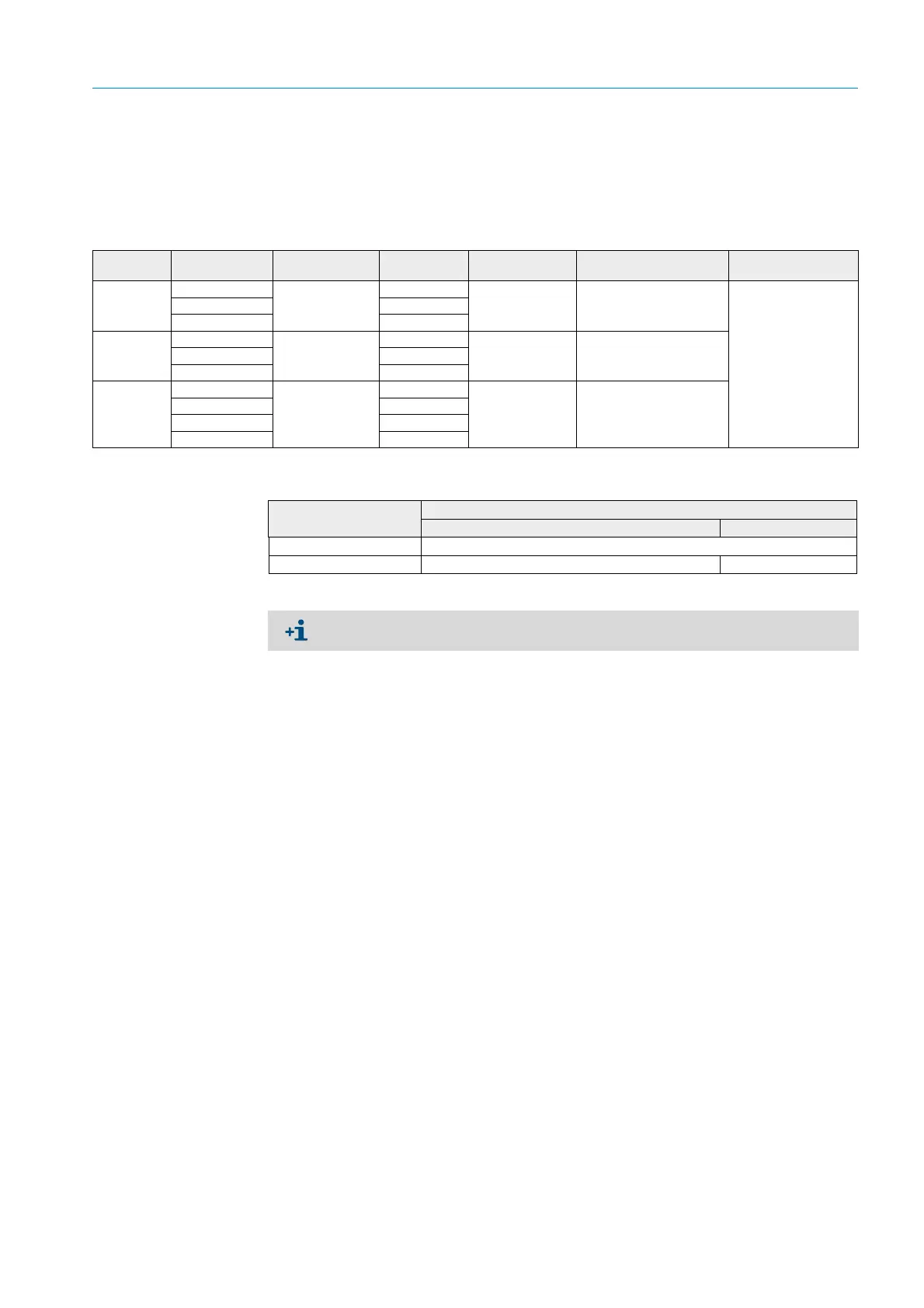
The device components required for a measuring system depend on the respective
application conditions. The following Table should serve to assist you in your selection.
Sender/receiver unit, reflector, flange with tube (standard components)
Voltage and purge air supply
Type Active
measuring path
Sender/receiver
unit
Reflector Line for reflector
connection
Type MCU Flange with tube
T50 0.5 ... 2.5 m DHT-T00 DHT-R50 - MCU-xxONN00000NNNE Flange with tube k100
1x each for sender/
receiver unit and
reflector
2 ... 5 m DHT-R51
4 ... 8 m DHT-R52
T100 0.5 ... 2.5 m DHT-T10 DHT-R00 - MCU-xxODN01000NNNE
2 ... 5 m DHT-R01
4 ... 12 m DHT-R02
T200 0.5 ... 2.5 m DHT-T21 DHT-R10 x MCU-xxODN01000NNNE
2 ... 5 m DHT-R11
4 ... 12 m DHT-R12
10 ... 50 m DHT-R13
Internal duct pressure Connection and supply components
Purge air Voltage
up to +2 hPa MCU-P + purge air hose (see “Installation accessories”, page 29)
> +2 hPa bis +30 hPa Optional external purge air unit MCU-N
We recommend using the optional external purge air unit when the sender/receiver unit
is more than 3 m away from the MCU control unit or reflector.
 Loading...


