47
8012428/YWL2/3-0/2016-08| SICK O P E R A T I N G I N S T R U C T I O N S | DUSTHUNTER T
Subject to change without notice
ASSEMBLY AND INSTALLATION 3
3.3.2 General information, prerequisites
All assembly work previously described must be completed (as far as applicable) before
starting installation work.
Carry out all installation work onsite unless otherwise explicitly agreed with SICK or
authorized representatives. This includes laying and connecting the power supply and
signal lines, installing switches and power fuses and connecting the purge air supply.
3.3.3 Installing the purge air supply
▸ Lay the purge air hoses with shortest paths and free of bends, shorten as required.
▸ Maintain sufficient distance from hot duct walls.
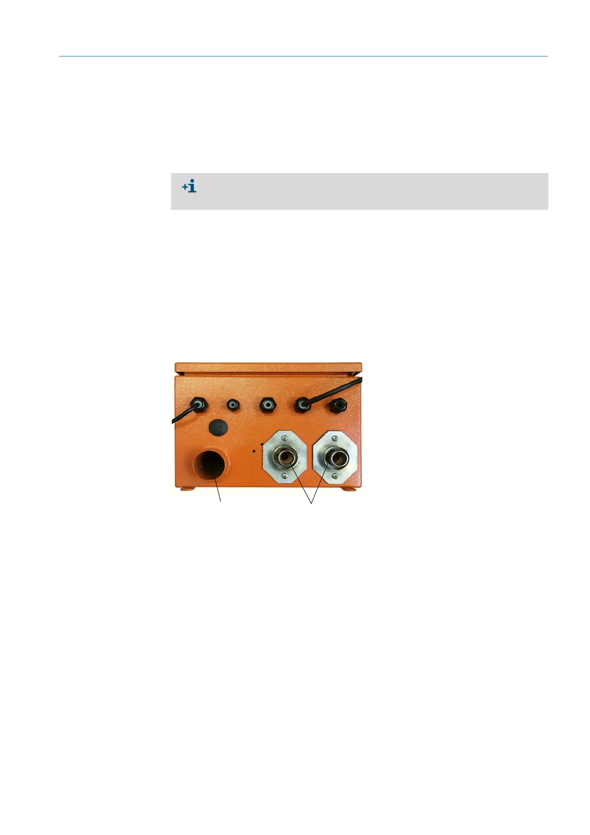
3.3.3.1 Control unit with integrated purge air supply (MCU-P)
Connect the DN40 purge air hose to the purge air outlets on the underside of the MCU-P
and secure with a strap retainer. Set the purge air outlets as shown (correct when nec-
essary).
Fig. 25: Underside of MCU-P
● Plan adequate line cross-sections (see “Technical Data”, page 112).
● Line ends with plugs to connect the sender/receiver unit must have sufficient free
length.
Purge air inlet
Purge air outlet DN 40
 Loading...


