50
8012428/YWL2/3-0/2016-08| SICKO P E R A T I N G I N S T R U C T I O N S | DUSTHUNTER T
Subject to change without notice
3 ASSEMBLY AND INSTALLATION
3.3.4 Connecting the MCU control unit
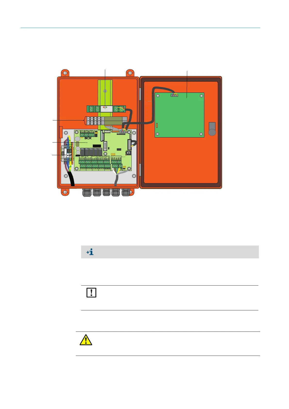
Fig. 28: Component layout in the MCU (without purge air supply, with options)
3.3.4.1 Work to be done
▸ Connect the connection line: see “Standard connection”, page 53.
▸ Connect lines for status signals (operation/failure, maintenance, function check, main-
tenance request, limit value), analog output, analog and digital inputs according to
requirements (see “Standard connection”, page 53, p. 56, Fig. 33 and Fig. “Terminal
assignment of analog input module”; only use shielded lines with twisted pairs).
▸ Connect power line to terminals L1, N, PE of the MCU (see “Component layout in the
MCU (without purge air supply, with options)”, page 50).
▸ Close off unused line openings with dummy plugs.
DISPLAYMODUL
relay 3 relay 4 relay 5
BUS
Ter m
Ter m
relay 1 relay 2
com nc. no.com nc. no. com nc. no.com nc. no. com nc. no.
Reset
Optional Interface module
Processor board
Optional Display module
Optional I/O modules
Terminals for power connection
If an onsite line is to be used, it must be connected to a suitable 7-pole socket (see
“Plug connector connection to onsite line”, page 52; SICK Part No.: 7045569).
NOTICE:
▸ Only use shielded lines with twisted pairs (e.g., UNITRONIC LiYCY (TP) 2 x
2 x 0.5 mm² from LAPPKabel; 1 pair of wires for RS 485, 1 pair of wires
for power supply; not suitable for underground laying).
WARNING:
▸ Be sure to check the wiring before switching the supply voltage on.
▸ Only modify wiring when disconnected from the power supply and potential-
free.
 Loading...


