93
8012428/YWL2/3-0/2016-08| SICK O P E R A T I N G I N S T R U C T I O N S | DUSTHUNTER T
Subject to change without notice
MAINTENANCE 5
5 Maintenance
5.1 General
The maintenance work to be carried out consists of:
● Cleaning work (see “Maintenance on the sender/receiver unit and reflector”, page 95),
● Securing the purge air supply function (see “Cleaning the optical interfaces on the
reflector”, page 99),
● Checking/correcting the alignment of the optical axes of sender/receiver unit and
reflector (see “Focussing the sender light beam for transmission measurement”,
page 64).
Take the following steps to set the measuring system to “Maintenance” mode before
starting maintenance work.
▸ Connect the MCU to the laptop/PC using the USB line and start program SOPAS ET.
▸ Connect with the MCU (see “Connection to the device via USB line”, page 58).
▸ Enter the Level 1 password (see “Password and operating levels”, page 86).
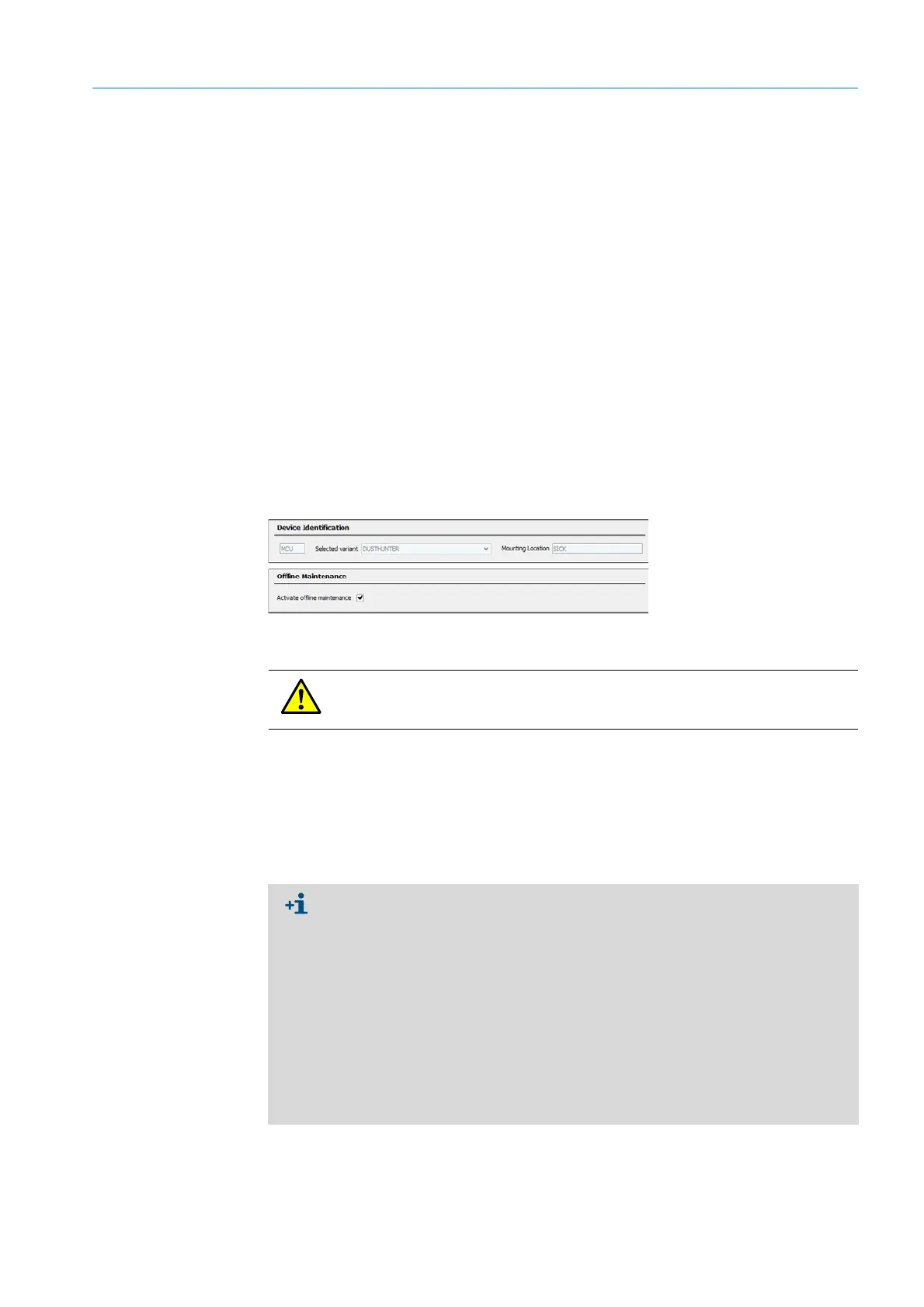
▸ Set the sender/receiver unit to “Maintenance”: Click “Maintenance sensor”)
Fig. 63: SOPAS ET menu: MCU/Maintenance/Maintenance
Resuming measuring operation
Resume measuring operation after completing the work (deactivate the “Maintenance on/
off” checkbox in the “Maintenance / Operation” window and click “Set State”).
WARNING:
Observe the relevant safety regulations as well as the safety notices (see “Responsibility
of user”, page 9) during all work.
● “Maintenance” mode can also be set using the buttons on the display on the MCU
(see “Menu structure”, page 87) when the LC-Display option is present or by con-
necting an external maintenance switch to the terminals for Dig In2 (17, 18) in the
MCU (see “Connecting the MCU control unit”, page 50).
● An automatic function check is not carried out during “Maintenance”.
● On DUSTHUNTER T200, the control window on the rear of the reflector (see “Sender
spot on reflector side (DUSTHUNTER T50)”, page 72) is lit for better inspection of the
optical alignment in the “Maintenance” mode.
● The value set for “Maintenance” is output on the analog output (see “Setting the
analog outputs parameters”, page 76). This is also applicable when a malfunction is
present (signaled on relay output).
● The “Maintenance” mode is reset when there is a voltage failure. In this case, the
measuring system switches automatically to “Measurement” after the operating volt-
age is switched on again.
 Loading...


