71
8012428/YWL2/3-0/2016-08| SICK O P E R A T I N G I N S T R U C T I O N S | DUSTHUNTER T
Subject to change without notice
START-UP AND PARAMETER SETTINGS 4
4.3 Sender/receiver unit and reflector
After completion of the tasks described above, the sender/receiver unit and the reflector
must be removed from the adjusting stands or zero tube and taken to the measuring
location.
4.3.1 Connection to the purge air supply
▸ Check whether the purge air supply is available (the flow direction must be correct and
the purge air hoses fitted tight on the connections).
▸ For purge air supply via the MCU-P control unit or external purge air supply, push the
purge air hose on the connections of the sender/receiver unit and the reflector and
secure with hose clamps.
For DUSTHUNTER T50, adapter DN 40 to DN 25 may be required.
4.3.2 Fitting and connecting on the duct
▸ Attach the sender/receiver unit and reflector to the flange with tube and secure with the
associated assembly kit (see “Assembly parts”, page 124), tighten the self-locking nuts
as tight as possible.
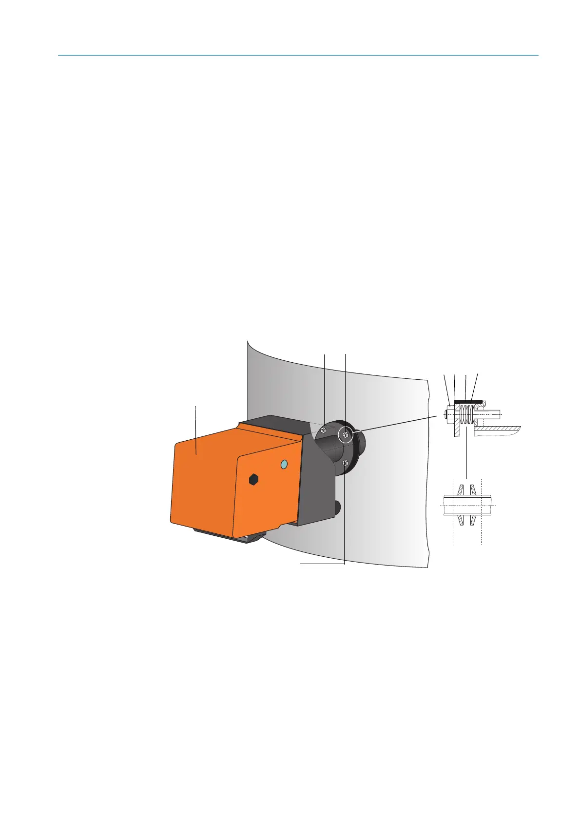
Fig. 46: Fitting the sender/receiver unit / reflector on the duct
C
AB
1 pair
Sender/receiver unit
Self-locking nut
Spherical washer
Sealing tape
Cup springs (4 pairs); only with fastening set for sender/receiver unit
A
Horizontal alignment
B
Fixing point
C
Vertical alignment
 Loading...


