2 Name of Each Part
2
2 Name of Each Part
2.1 Entire Assembly
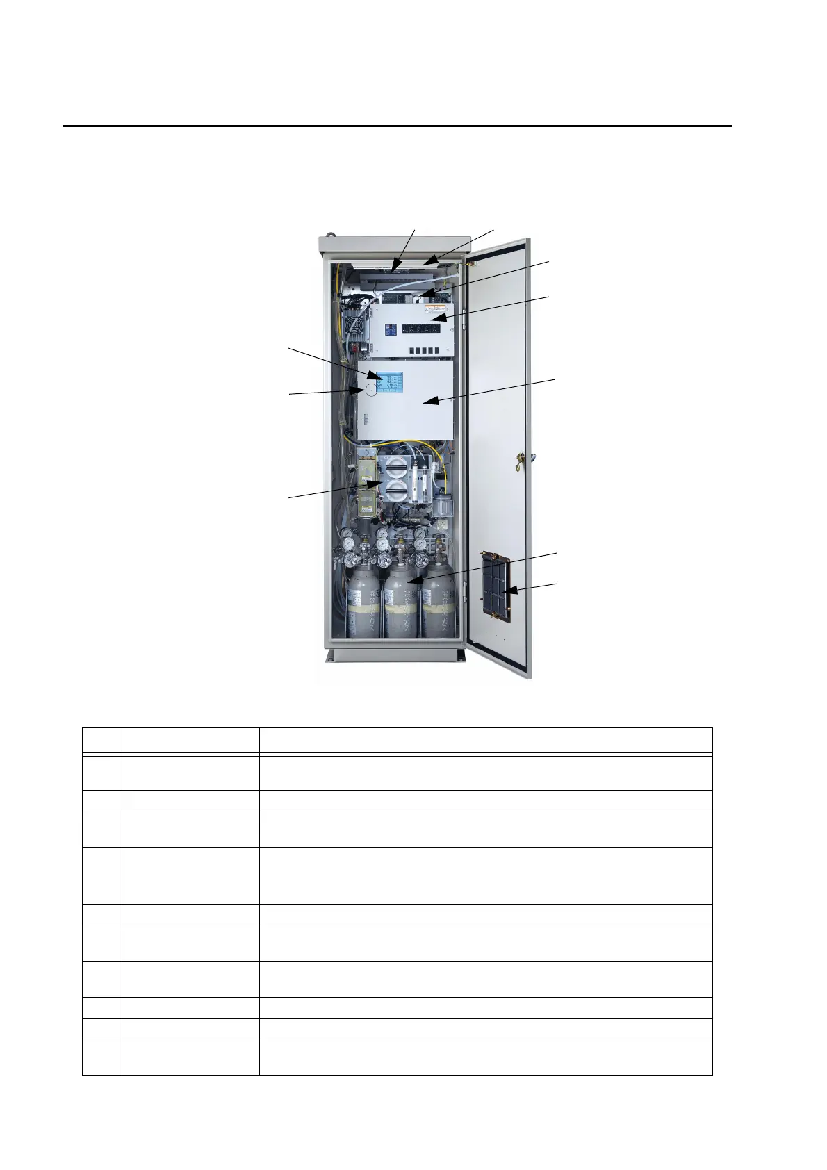
Fig. 1 Entire view of instrument
No. Name Description
1 Analyzer cabinet
A cabinet incorporating the optical instrument.
The module of 5 components at maximum is incorporated.
2 Operation screen LCD screen with touch-panel display.
3 Status indicator
Indicates the power ON/OFF state and the operation status of analyzer.
Refer to " Q Warm-up and preparation" (page 9).
4 Sampling unit
Introduces sample gas and reference gas into the analyzer.
Performs the gas processing: Drain separation → Sulfuric mist processing →
NO
2
to NO conversion → Dust removal processing → Cooling
5 Panel switch Refer to " 2.2 Panel Switch in Cabinet " (page 3).
6 Cylinder container
A space containing high-pressure gas cylinder.
Maximum 6 cylinders of 3.4 L can be mounted according to the cabinet size.
7 Input/Output terminal
A connection part of: analyzer power, primary filter heater power, heated tube
power (optional).
8 Fluorescent lamp Illumination inside the cabinet.
9 Ventilation fan A ventilation fan inside the cabinet.
10 Ventilation filter
A filter to ventilate inside the cabinet.
Refer to " 7.3.6 Cleaning the cabinet ventilation filter " (page 66).
5
1
6
2
4
7
8
10
3
9
 Loading...


