62
8012428/YWL2/3-0/2016-08| SICKO P E R A T I N G I N S T R U C T I O N S | DUSTHUNTER T
Subject to change without notice
4 START-UP AND PARAMETER SETTINGS
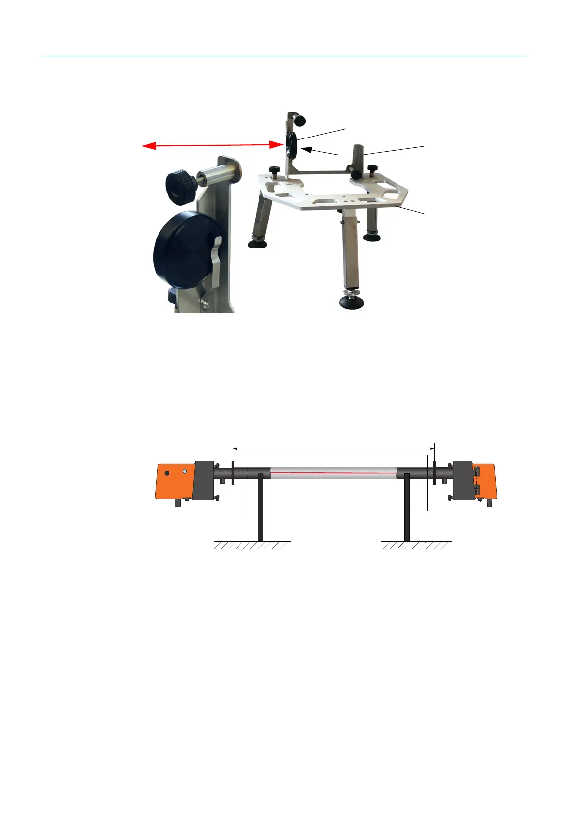
Fig. 36: Assembly of the DHT-R5x reflector on the adjusting stand
– Onsite installation of a “zero tube”.
The tube must fit on the flange tubes and have little reflection inside.
Fig. 37: Assembly on a dust-free path with zero tube (shown for DUSTHUNTER T100)
▸ Using the associated connection lines, connect the sender/receiver unit to the MCU and
also the reflector to the sender/receiver unit for DUSTHUNTER T200.
▸ Connect the MCU to the supply voltage.
▸ Start the SOPAS ET program and connect to the measuring system (see “Connection to
the device via USB line”, page 58).
▸ Enter the Level 1 password (see “Password and operating levels”, page 86).
▸ Set the sender/receiver unit to “Maintenance”: Click “Maintenance sensor”.
A
A
Optical axis
Reflector DHT-R5x
Bracket for reflector DHT-R5x
Adjusting stand
 Loading...


