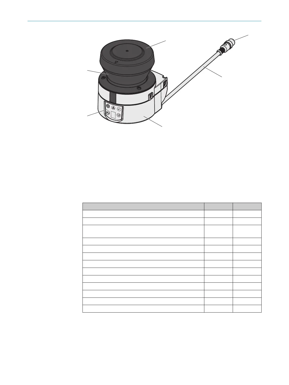
Figure 4: Device components
1
Optics cover
2
Round plug connector
3
Light emission window
4
Connecting cable
5
LEDs and 7-segment display
6
Sensor
3.2.3 Functions
Table 1: Functions
Function Standard Remote
Protective field range, radial [m] 1, 2, 3 2, 3
Warning field range, radial
1)
[m] 8 8
Object resolution [mm] 30, 40, 50,
70, 150
2)
30, 40, 50,
70, 150
2)
Output signal switching device pairs (OSSDs) 1 -
External device monitoring (EDM) ✓
3)
-
Universal I/Os 2 -
Restart interlock/delay ✓
3)
-
Field sets comprising one protective field and 2 warning fields 1 16
Monitoring cases 1 32
Output for warning field interruption
✓
-
EFI interface (safe SICK device communication) -
✓
Park mode, activation by monitoring case -
✓
Standby, activation by EFI bit or standby input ✓
3)
✓
1)
Warning field range for a radiance factor of 30% (see "Char
acteristic curves", page 113).
2)
150 mm resolution configurable only for the Long Range variant with a 3 m scanning range.
3)
Availability depends on the configuration of the universal I/Os (see "Universal I/O connections",
page 78).
3.2.4 Scanning ranges
The device variants differ with regards to their maximum scanning range and the resul‐
t
ant protective field size.
3 P
RODUCT DESCRIPTION
16
O P E R A T I N G I N S T R U C T I O N S | S300 Mini 8014170/ZA23/2019-11-14 | SICK
Subject to change without notice