NOTE
b
Mount t
he device so that it is protected from moisture, dirt, and damage.
b
Mount the sensor so that the status indicators can be clearly seen.
b
Avoid exposing the device to excessive shock and vibration.
b
For systems that vibrate heavily, use shock absorbers to prevent the possibility of
fixing screws unintentionally coming loose.
b
Regularly check the tightness of the fixing screws.
b
Observe the maximum permissible tightening torque of 5.9 Nm for the M5 fixing
screws on the device.
Further topics
•
"Dimensional drawings", page 120
•
"Brackets", page 124
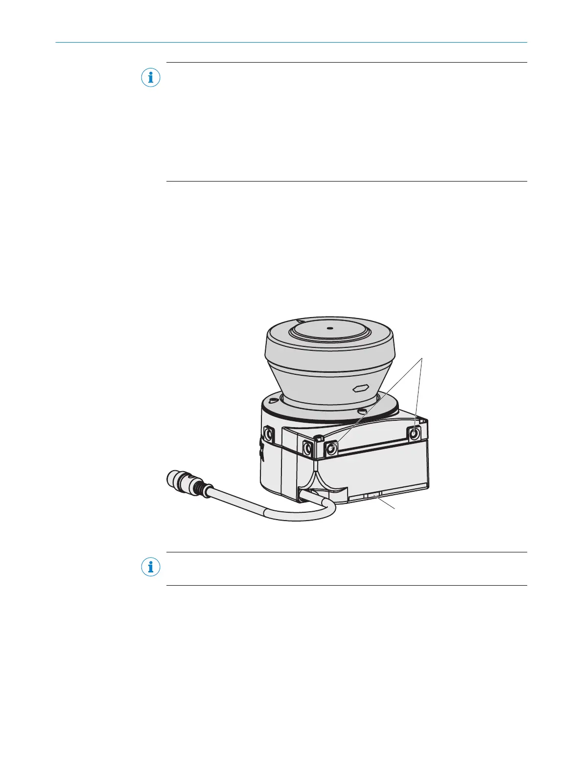
5.2.1 Direct mounting
The device has two M5 × 8 threaded holes on the rear. They can be used to mount the
de
vice directly on the intended mounting surface. To avoid a possible tendency to
vibrate, the reference surface located on the rear can be used as a third support point
if necessary 1.
Figure 48: Direct mounting
NOTE
W
hen mounting the device, observe the dimensional drawings.
Further topics
•
"Dimensional dr
awings", page 120
5.2.2 Mounting using mounting kit 1a or 1b
Overview
Y
ou can use mounting kit 1 to mount the device indirectly on the mounting surface. The
mounting kit is available as mounting kit 1a without a protective device for the optics
cover and as mounting kit 1b with a protective device for the optics cover.
5 MOUN
TING
60
O P E R A T I N G I N S T R U C T I O N S | S300 Mini 8014170/ZA23/2019-11-14 | SICK
Subject to change without notice