Schematic legend
T
able 5: Schematic legend for connection diagrams
Meaning
k1 and k2 or k3 and k4 Output circuits
Incor
porate these contacts into the controller in such a way that
the dangerous state is brought to an end if the output circuit is
open. For categories 3 and 4, they must be incorporated on dual-
channels (x, y paths) in accordance with EN 13849-1. Observe the
maximum values when loading the outputs (see "Data sheet",
page 108).
FE Functional earth
T
o achieve the specified EMC safety, the functional earth (FE)
must be connected, e.g., to the central earth star point of the vehi‐
cle or system.
Hx Signaling device, e.g., for Reset required, fault or contamination
Sx Control switches, e.g., for reset or signaling device for monitoring
c
ase switching
Restart interlock and external device monitoring
BN
GN
YE
PK
BU
FE
WH
GY
k2k1
x
x
y
y
z
z
k2
k1
1)
S300 Mini Standard
E112600/00/2014-03-06
S1
2
3
4
5
6
7
H
1
K1 K2 H1
k1
k2
H = Housing
+24 V
F
E
0 V
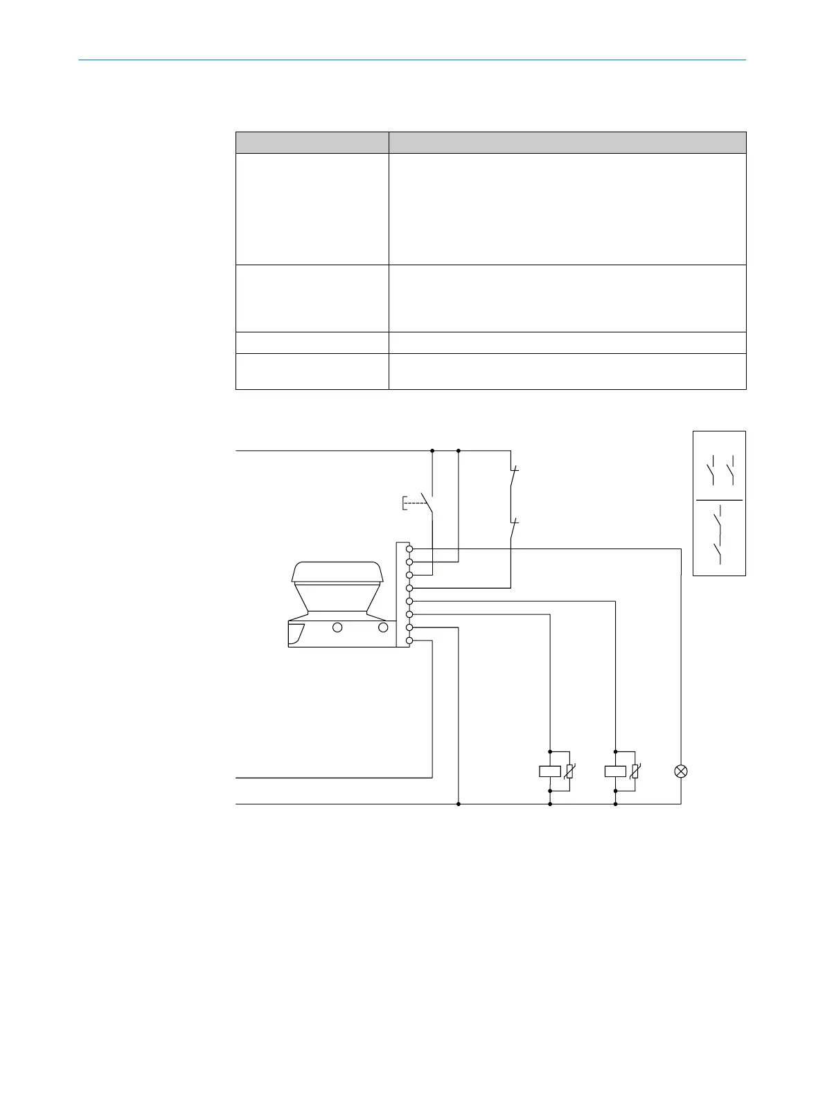
Figure 41: Connection diagram for restart interlock and external device monitoring
S300 Mini S
tandard in conjunction with relays (contactors); Operating mode: with
restart interlock (universal I/O 1 must be configured as reset) and external device moni‐
toring (universal I/O 2 must be configured as EDM).
PROJECT PLANNING 4
8014170/ZA23/2019-11-14 | SICK O P E R A T I N G I N S T R U C T I O N S | S300 Mini
53
Subject to change without notice