NOTE
b
L
ay all cables and connecting cables so that they are protected from damage.
b
If you are using the safety laser scanner to protect hazardous areas: Make sure
that the connected controller and all devices responsible for safety also comply
with the required category according to ISO 138491 and the required performance
level according to ISO 13849.
b
If you are using shielded cables, connect the shield to the terminal over a large
area.
b
Make sure that the safety laser scanner is provided with appropriate electrical
fuse protection.
NOTE
•
T
he power supply unit must be able to bridge a power failure of 20 ms.
•
The power supply unit must provide safe isolation (SELV/PELV). Suitable power
supply units are available as accessories from SICK (see "Accessories",
page 123).
Further topics
•
"Data sheet", page 108
6.2 Pin assignment
Overview
All in
puts and outputs of the device are located on the round plug connector of the con‐
necting cable. Connect the device using pre-assembled extension cables (see table 7,
page 66, see table 9, page 68).
The round plug connector has different pin assignments depending on the variant.
NOTE
•
All in
puts and outputs of the device must be used only in the specified manner.
•
The round plug connectors are coded. If you use any plug connectors other than
the ones intended, any warranty claim against SICK AG shall become void.
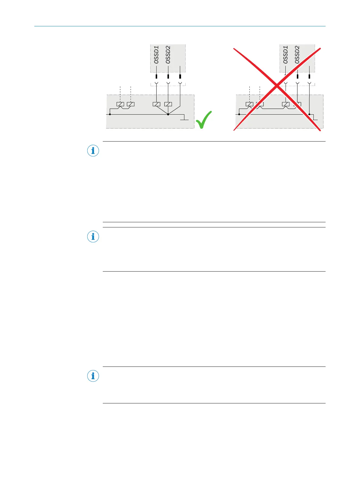
Wiring in accordance with EMC regulations
T
he quality of the shield is essentially dependent on the quality of the connection of the
screen. In general, the best shielding effect can only be achieved by applying the screen
at both ends using large area connections.
ELECTRICAL INSTALLATION 6
8014170/ZA23/2019-11-14 | SICK O P E R A T I N G I N S T R U C T I O N S | S300 Mini
65
Subject to change without notice