b
If it is no
t possible to connect the screen via threaded fittings (e.g. on bus nodes),
connect the screen physically close to the device using a metal clamp, e.g., to a
control cabinet chassis.
NOTE
•
If y
ou want to operate two safety laser scanners in a system (communication via
EFI), then the same earthing method must be used for both safety laser scanners.
•
If there is a protection earth (PE) in an installation, it can be used to connect the
functional earth (FE). A functional earth connection (FE) must never be used as a
protection earth (PE), however.
Functional earth
T
o achieve the specified EMC safety, the functional earth (FE) must be connected, e.g.,
to the central earth star point of the vehicle or system.
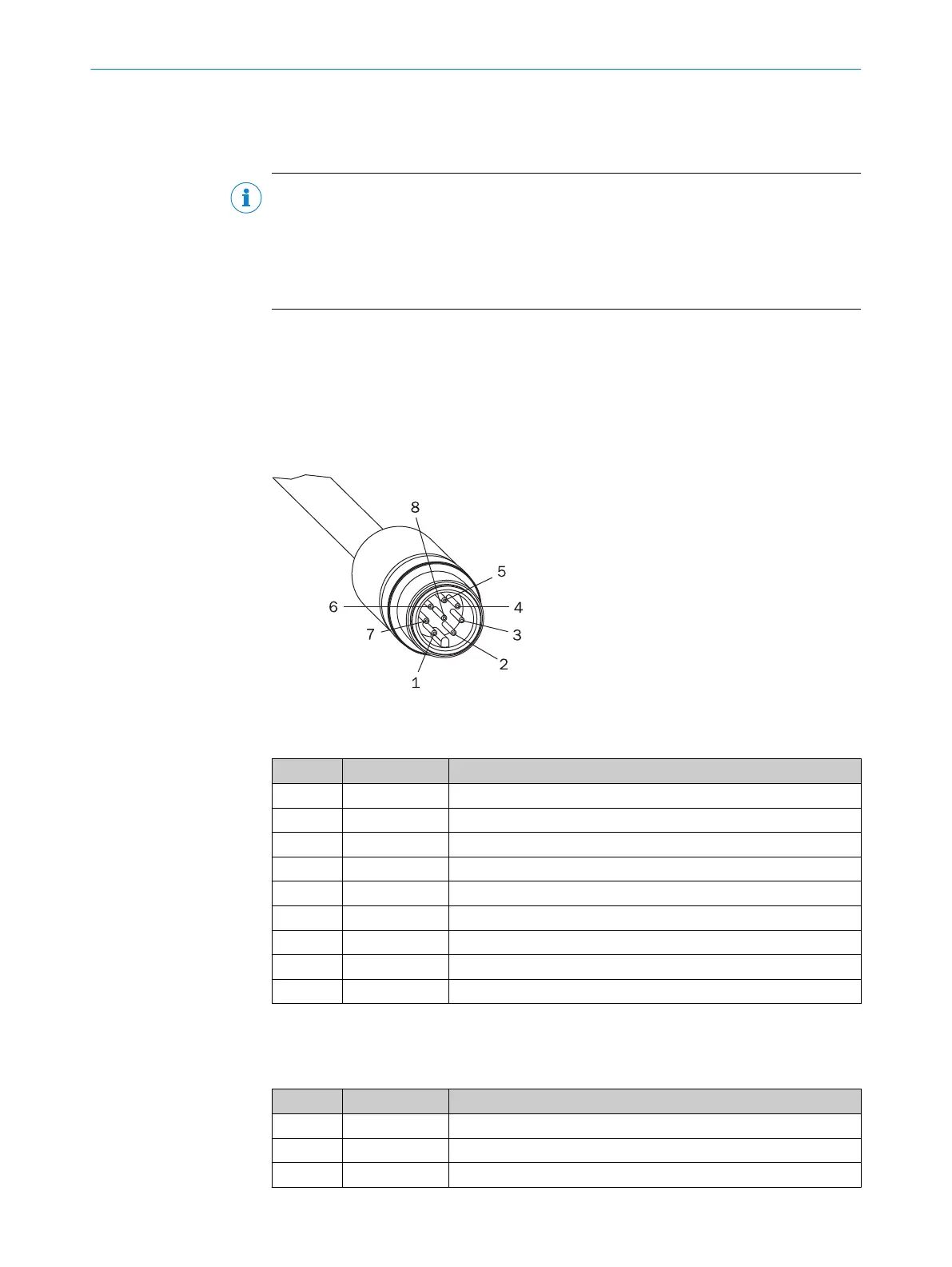
6.2.1 Round plug connector of the S300 Mini Standard
Pin assignment
Figure 51: Round plug connector of the S300 Mini Standard
T
able 6: Pin assignment of the S300 Mini Standard
Pin Signal Function
1 WF Output for warning field 1
2 24 V DC Supply voltage for the S300 Mini
3 I/O1 Universal I/O
4 I/O2 Universal I/O
5 OSSD1 Output signal switching device
6 OSSD2 Output signal switching device
7 0 V DC Supply voltage
8 FE/screen Functional earth/screen
Housing FE/screen Functional earth/screen
Recommended cables for connecting the S300 Mini Standard: extension cables with A-
codin
g, see table 34, page 123.
Table 7: Core assignment of the S300 Mini Standard extension cable
Wire Color Function
1 White Output for warning field 1
2 Brown 24 V DC supply voltage
3 Green Universal I/O connection 1
6 ELECTRICAL INSTALLATION
66
O P E R A T I N G I N S T R U C T I O N S | S300 Mini 8014170/ZA23/2019-11-14 | SICK
Subject to change without notice