EasyManua.ls Logo

SICK S300 Mini User Manual

SICK S300 Mini
140 pages
To Next Page IconTo Next Page
To Previous Page IconTo Previous Page
Page #76 background imageLoading...
Page #76 background image
restart. External device monitoring is then able to detect if one of the contactor’s con‐
t
acts is welded, for instance. In this case the external device monitoring places the sys‐
tem in a safe operational status and the OSSDs are not switched back to the ON state.
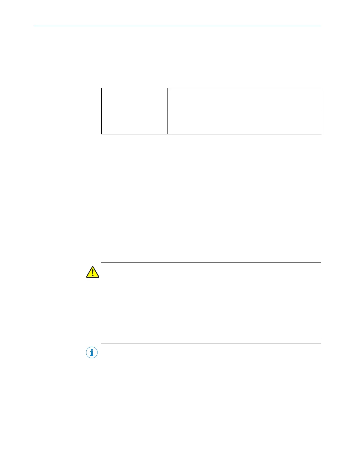
The table shows how the device reacts if the external device monitoring detects a con‐
tactor malfunction:
Table 16: Behavior of the device on a contactor malfunction
Without internal restart
int
erlock or with restart
delay
T
he system locks completely (lock-out).
The error message appears in the 7-segment display.
With restart interlock
T
he safety laser scanner switches its OSSDs to the OFF state.
The LED Ê is illuminated.
The error message appears in the 7-segment display.
External device monitoring can be configured in the CDS.
Further topics
"C
onnection diagrams", page 52
7.8 Restart
Overview
Y
ou can configure the restart behavior as follows:
Without restart interlock
With restart delay
With restart interlock
The type of restart can be configured in the CDS.
Important information
DANGER
H
azard due to unexpected starting of the machine
If the protective field can be exited in the direction of the hazardous point, e.g., to areas
that are unprotected due to the method of mounting or the near range of the safety
laser scanner, the machine could restart while a person is in the hazardous area.
b
It is imperative that you configure the safety laser scanner with restart interlock if
the protective field can be exited in the direction of the hazardous point or if a per‐
son cannot be detected by the safety laser scanner at every point in the hazardous
area.
NOTE
T
he S300 Mini Remote can only be operated on an S3000 / S300 safety laser scanner,
on a Flexi Soft safety controller, or on a sens:Control device via EFI. If a restart interlock
is needed, then it must be configured and installed on this device.
Configuration of the safety laser scanner without restart interlock
If t
here is an object in the protective field, the OSSDs on the safety laser scanner switch
to the OFF state. The OSSDs are re-enabled again immediately when there is no longer
an object in the active protective field.
7 C
ONFIGURATION
76
O P E R A T I N G I N S T R U C T I O N S | S300 Mini 8014170/ZA23/2019-11-14 | SICK
Subject to change without notice

Table of Contents

Other manuals for SICK S300 Mini

Questions and Answers:

SICK S300 Mini Specifications

General IconGeneral
TypeSafety laser scanner
Angular Resolution0.5°
Number of Scanning Lines1
Protection RatingIP65
Number of Field Sets2
Scanning Angle270°
Wavelength905 nm
Power Supply24 V DC
Housing MaterialPlastic
Output SignalOSSD
Operating Temperature0°C to +50°C
Response Time≤ 100 ms
Supply Voltage24 V DC

Summary

Safety information

General safety notes

Covers essential safety precautions for operating the laser scanner.

Intended use

Details the approved applications and limitations for the safety laser scanner.

Inappropriate use

Lists unsuitable applications and conditions where the device should not be used.

Applications of the device

Describes the device's suitability for various safety functions and environments.

Requirements for the qualification of personnel

Specifies the necessary qualifications for personnel involved in installation and operation.

Product description

Construction and function

Explains the operating principle and physical components of the safety laser scanner.

Product characteristics

Details the key features, variants, and overview of the S300 Mini scanner.

Specific features

Highlights unique attributes like scanning angle, dust tolerance, and configuration methods.

Functions

Lists the available functions for the Standard and Remote variants of the S300 Mini.

Protective field, warning field and field set

Explains the configuration and purpose of protective and warning fields.

Project planning

Design

Covers critical design considerations for implementing the safety laser scanner.

Measures to prevent unsecured areas

Discusses methods to ensure complete coverage and avoid blind spots.

Timing for monitoring case switching

Explains how to manage timing for seamless switching between monitoring cases.

Protective field size

Guides on calculating and setting the protective field size for safety.

Minimum distance

Explains the calculation of minimum safety distances for hazardous point protection.

Integration in electrical control

Guides on connecting the safety laser scanner within electrical control systems.

Connection diagrams

Provides schematics for various electrical integration and monitoring scenarios.

Mounting

Electrical installation

Configuration

OSSDs

Discusses Output Signal Switching Devices (OSSDs) and their behavior.

External device monitoring (EDM)

Explains how EDM checks the status of downstream contactors.

Restart

Details the configuration options for restart behavior (interlock, delay).

Field Sets

Explains the concept of field sets for defining protective and warning areas.

Configuring the protective field and warning field

Guides on setting up protective and warning fields using the CDS.

Monitoring cases

Explains how multiple monitoring cases can be configured for different situations.

Commissioning

Safety

Emphasizes safety checks and procedures before initial commissioning.

Test notes

Provides important notes and procedures for testing before commissioning.

Tests before initial commissioning

Details the essential checks required before the first use of the system.

Maintenance

Safety

Highlights safety precautions to be observed during maintenance activities.

Regular inspection

Covers scheduled inspections by qualified personnel to ensure ongoing safety.

Regular inspection of the protective device by qualified safety personnel

Details the process and frequency for safety inspections by qualified personnel.

Daily check of the protective device by authorized and specialist personnel

Outlines daily checks to be performed by authorized personnel to verify functionality.

Troubleshooting

Response to errors

Offers guidance on how to react to machine malfunctions and errors.

Technical data

Accessories

Annex

Checklist for initial commissioning and commissioning

Offers a checklist for manufacturers and installers to ensure proper commissioning.

Related product manuals