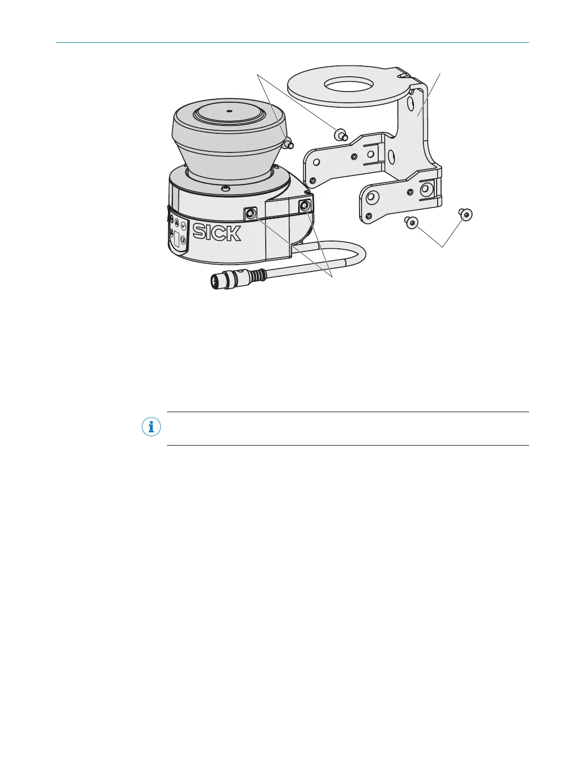
Figure 49: Mounting using mounting kit 1b including optics cover protection
1
Fixing screws
2
Mounting kit 1b
3
Threaded holes M5×8
Approach
1.
Mount kit 1a or 1b on the mounting surface.
2. Mount the safety laser scanner on mounting kit 1a or 1b.
NOTE
W
hen mounting the device, observe the dimensional drawings.
Further topics
•
"Dimensional dr
awings", page 120
5.2.3 Mounting using mounting kits 2 and 3
Overview
Y
ou can use mounting kits 2 and 3 (only in conjunction with mounting kit 1a or 1b) to
align the device in 2 planes. The maximum adjustment angle is ± 11° in both planes.
MOUNTING 5
8014170/ZA23/2019-11-14 | SICK O P E R A T I N G I N S T R U C T I O N S | S300 Mini
61
Subject to change without notice