Restart interlock and external device monitoring in conjunction with a UE10 safety
r
elay
UE10-3OS
H1
S
1
B1 B3 Y1 13 3323 41
B2 B4 Y2 14 3424 42
+24 V
FE
0 V
E112608/00/2014-03-06
BN
GN
YE
PK
BU
FE
WH
GY
S300 Mini Standard
2
3
4
5
6
7
H
1
H = Housing
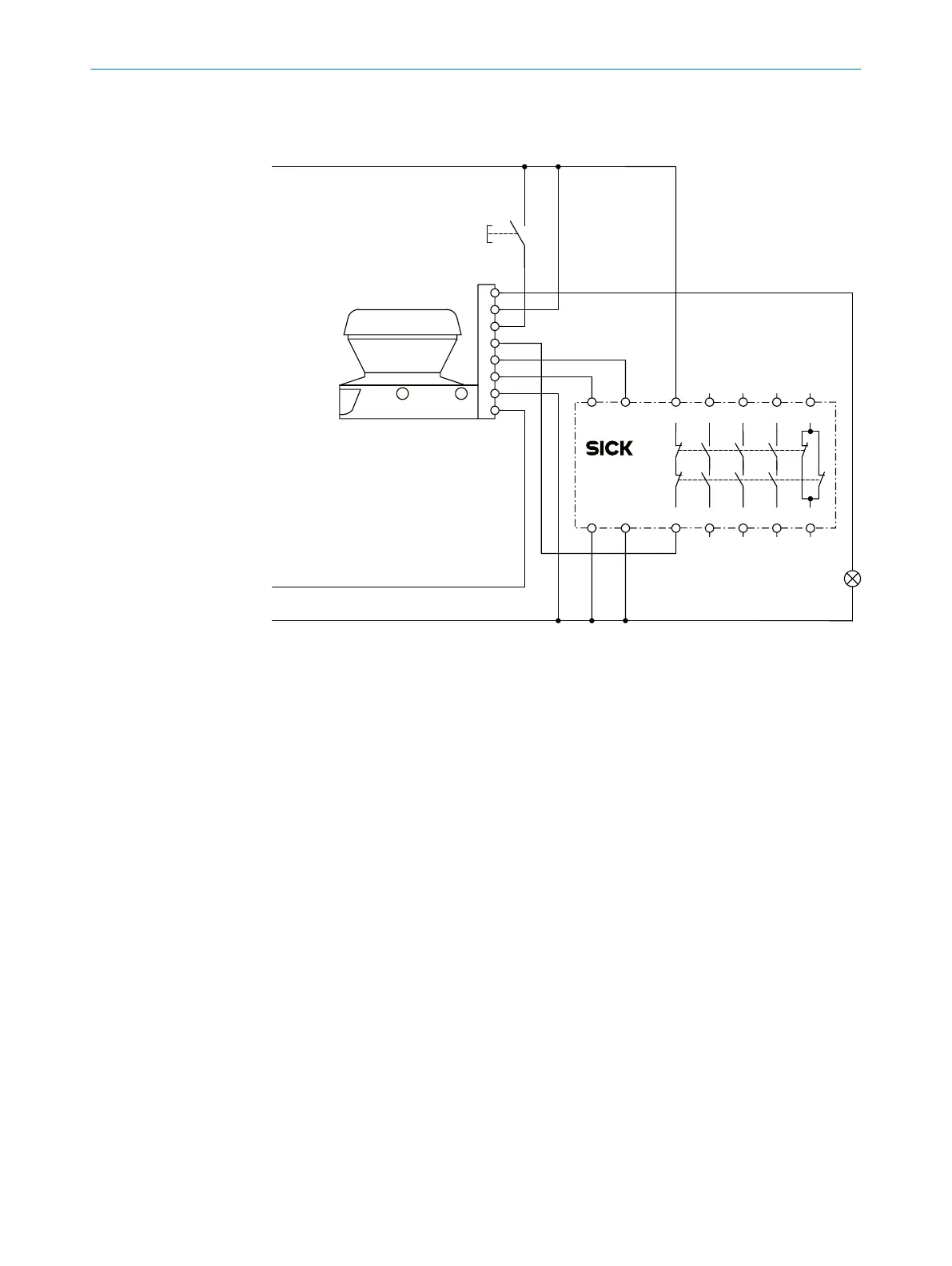
Figure 42: Connection diagram for restart interlock and external device monitoring in conjunction
w
ith a UE10 safety relay
S300 Mini Standard in conjunction with UE10-3OS; Operating mode: with restart inter‐
lock (universal I/O 1 must be configured as reset) and external device monitoring (uni‐
versal I/O 2 must be configured as EDM).
4 P
ROJECT PLANNING
54
O P E R A T I N G I N S T R U C T I O N S | S300 Mini 8014170/ZA23/2019-11-14 | SICK
Subject to change without notice