Wire Color Function
4 Yellow Universal I/O connection 2
5 Gray Output signal switching device OSSD1
6 Pink Output signal switching device OSSD2
7 Blue Supply voltage 0 V DC
8 FE/screen Functional earth/shield
Universal I/O connections of the S300 Mini Standard
DANGER
Ine
ffectiveness of the protective device
In the case of non-compliance, it is possible that the dangerous state of the machine
may not be stopped or not stopped in a timely manner.
The universal I/O connection outputs are purely application diagnostics outputs, e.g.,
for transmitting information to controllers.
b
Do not use the universal I/O connection outputs for safety-related tasks.
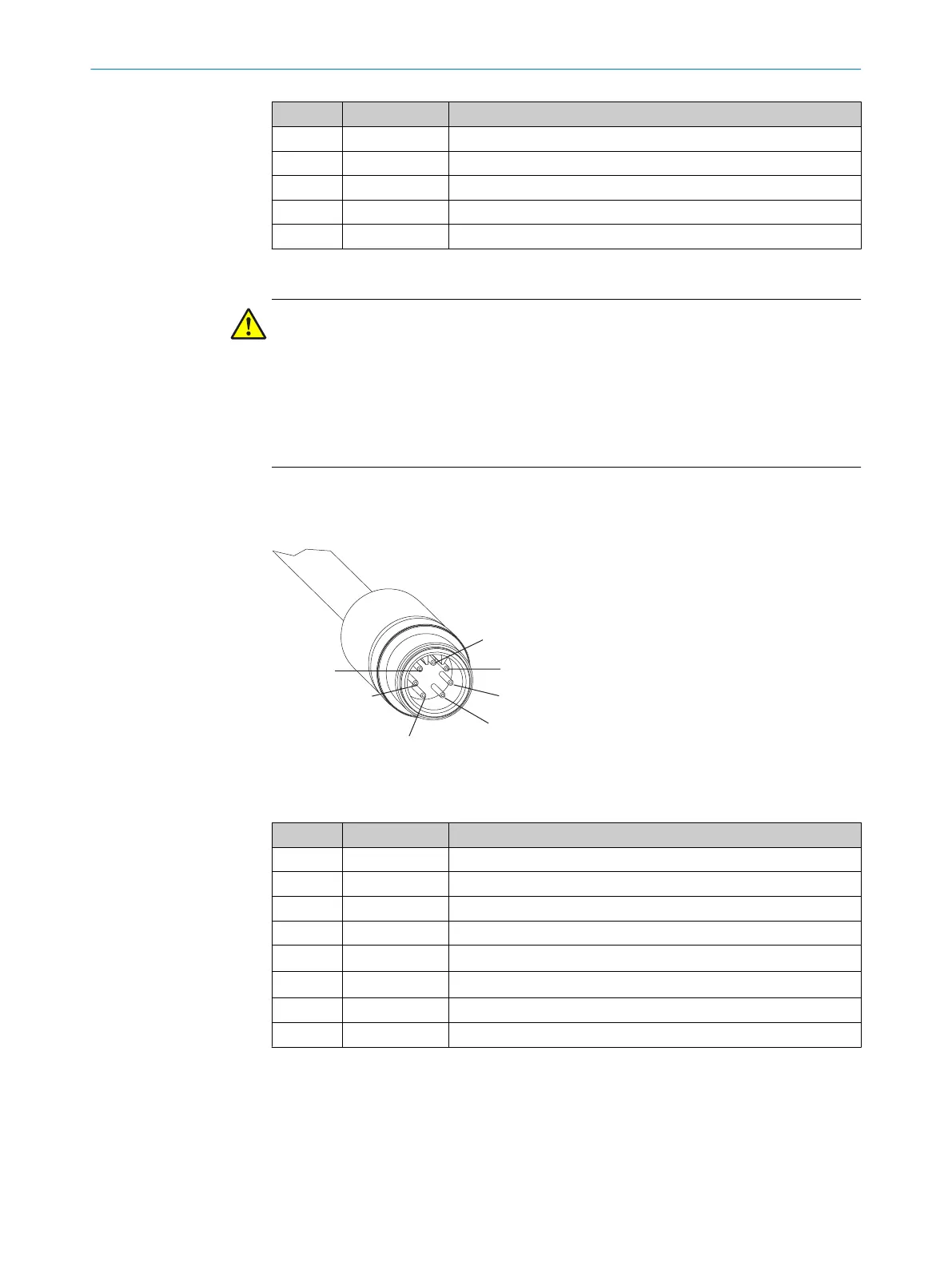
6.2.2 Round plug connector of the S300 Mini Remote
Pin assignment
Figure 52: Round plug connector of the S300 Mini Remote
T
able 8: Pin assignment of the S300 Mini Remote
Pin Signal Function
1
1)
H/G Host/guest input
2 24 V DC Supply voltage for the S300 Mini
3 – Not assigned
4 – Not assigned
5 EFI
B
Enhanced function interface
6 EFI
A
Enhanced function interface
7 0 V DC Supply voltage
Housing FE/screen Functional earth/screen
1)
For the unambiguous identification of the S300 Mini in the EFI system.
ELECTRICAL INSTALLATION 6
8014170/ZA23/2019-11-14 | SICK O P E R A T I N G I N S T R U C T I O N S | S300 Mini
67
Subject to change without notice