45
SITRANS F M
5. Installation of sensor
MAG 3100
(PTFE liner and PFA)
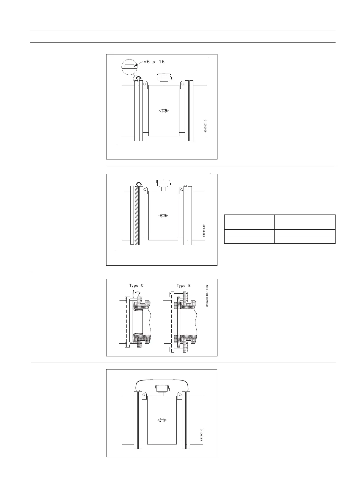
Electrically conductive piping
Use an earth strap on one side.
Potential equalization, electrically conductive
pipe
Non-conductive piping
Use an earthing flange. Place the flange between
flowmeter and the adjacent pipe flange.
Selection of earthing flange depends on the
medium, liner material and application, see
figure.
Special attention must be given to systems with
cathodic protection.
Compact installation:
The transmitter must be supplied through an
isolation transformer. The terminal "PE" must
never be connected.
Remote installation:
The screen must only be connected at the
sensor end via a 1.5 μF condensator. The
screen must never be connected at both ends.
Isolated sensor:
If above mentioned connections are unaccept-
able, the sensor must be isolated from the pipe
work.
The bolts must be isolated from pipe.
Liner Suitable
material earthing flange
PTFE Type E
PFA Flat ring
Type of earthing flange depending on liner
material
With abrasive liquids, flowmeter inlet protection
may be necessary. Here type C and E earthing
flanges are used.
Type C (for all liners except PTFE and PFA) is
clamped between the flanges.
Type E (for PTFE liner only) is fitted to the
flange.
Flat ring (for PFA liner only) is fitted to the
flange.
When using an earthing flange, gaskets must
always be used between the adjacent pipe
flange and the earthing flange.
5.2
Inlet protection MAG 3100
5.3
Cathodic protected piping
 Loading...


