EasyManuals Logo

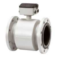
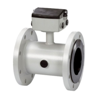
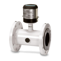
Siemens MAG 5000 User Manual

Siemens MAG 5000
665 pages
To Next Page IconTo Next Page
To Previous Page IconTo Previous Page
Page #133 background imageLoading...
Page #133 background image
58
SITRANS F M
7. Electrical connection
... ...
...
Shield
7. Electrical connection
7.1
Transmitter
MAG 5000 and MAG 6000
connection diagram
Note
Special cable with individual
wire shields (shown as
dotted lines) are only
requried when using empty
pipe function or long cables.
(See “Technical data”
chapter 2 for further details.)
Potential Hazards
Grounding
The mains protective earth wire must be connected to the PE terminal in accordance with the
diagram (class 1 power supply).
Mechanical counters
When mounting a mechanical counter to terminals 57 and 58 (active output), a 1000 μF capacitor
must be connected to the terminals 56 and 58.
Capacitor + is connected to terminal 56 and capacitor to terminal 58.
Output cables
If long cables in noisy environment, we recommend to use screened cable.
Electrodes cables
Dotted connections only to be made when using special electrode cable.

Table of Contents

Other manuals for Siemens MAG 5000

Questions and Answers:

Question and Answer IconNeed help?

Do you have a question about the Siemens MAG 5000 and is the answer not in the manual?

Siemens MAG 5000 Specifications

General IconGeneral
TypeElectromagnetic Flowmeter
Protection ClassIP67
MaterialStainless Steel, Carbon Steel
Power Supply24 V DC, 100-240 V AC
Accuracy±0.2% of flow rate
CommunicationHART, PROFIBUS, Modbus
Enclosure RatingIP67
Ambient Temperature Range-20°C to +60°C
SizesDN 2 to DN 3000
Lining MaterialsPTFE, Hard Rubber
Electrode MaterialsStainless Steel, Hastelloy, Tantalum
Process Temperature-40 to +180 °C (-40 to +356 °F) depending on liner
Process PressureUp to 40 bar (580 psi)
ApprovalsATEX, FM, CSA, IECEx
Flow Velocity Range0 to 12 m/s
Output Signals4-20 mA, Pulse, Frequency

Related product manuals