EasyManuals Logo

Siemens MAG 5000 User Manual

Siemens MAG 5000
665 pages
To Next Page IconTo Next Page
To Previous Page IconTo Previous Page
Page #253 background imageLoading...
Page #253 background image
7ML19981FB05 MultiRanger 100/200 – INSTRUCTION MANUAL Page 79
mmmmm
Open Channel Monitoring
MR 200
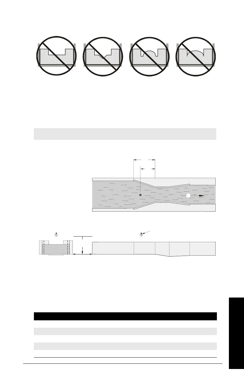
Non-Applicable Weir Profiles
Flows through these weirs can be measured using the Universal Flow Calculation P600 =
4 or 5. See
Universal Calculation Support
on page 82.
Parshall Flume
Application Information
Sized by throat width
Set on solid foundation
For rated flows under free flow conditions, the head is measured at
2
/
3
the length of
the converging section from the beginning of the throat section
Note: C = Converging Dimension.
Parameter Index Value
P600 G 1–Parshall Flume
P601 G 1.22–1.607 (consult your flume documentation)
P603 G Maximum Head
P604 G Maximum Flow (Q)
P606 G Time Units
contracted
rectangular
compound Poebing
approximate
exponential
Flow
C
2
/
3
C
P006
Front View
Plan View
Transducer
Side View

Table of Contents

Other manuals for Siemens MAG 5000

Questions and Answers:

Question and Answer IconNeed help?

Do you have a question about the Siemens MAG 5000 and is the answer not in the manual?

Siemens MAG 5000 Specifications

General IconGeneral
TypeElectromagnetic Flowmeter
Protection ClassIP67
MaterialStainless Steel, Carbon Steel
Power Supply24 V DC, 100-240 V AC
Accuracy±0.2% of flow rate
CommunicationHART, PROFIBUS, Modbus
Enclosure RatingIP67
Ambient Temperature Range-20°C to +60°C
SizesDN 2 to DN 3000
Lining MaterialsPTFE, Hard Rubber
Electrode MaterialsStainless Steel, Hastelloy, Tantalum
Process Temperature-40 to +180 °C (-40 to +356 °F) depending on liner
Process PressureUp to 40 bar (580 psi)
ApprovalsATEX, FM, CSA, IECEx
Flow Velocity Range0 to 12 m/s
Output Signals4-20 mA, Pulse, Frequency

Related product manuals