46
SITRANS F M
6. Installation of transmitter
6. Installation of
transmitter
6.1
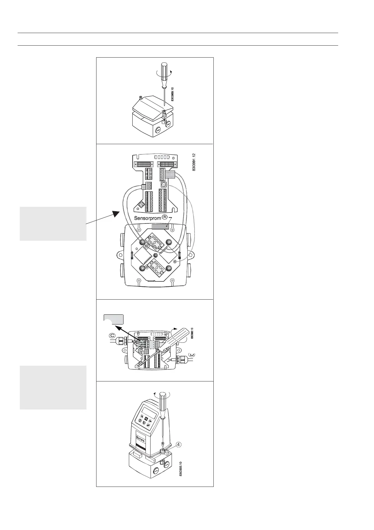
Compact installation
MAG 5000 and MAG 6000
Compact polyamide
Step 1
Remove and discard the terminal box lid of the
sensor.
Fit the M20/½NPT cable glands for the supply
and output cables.
Step 2
Remove the two black plug assemblies for coil
and electrode cables in the terminal box and
connect them to their corresponding terminal
numbers on the connection board.
Step 3
Connect earth wire on connection board to
bottom of connection box.
Connect the 2 pin connector and 3 pin connector
as shown.
Note
In earlier version the 3 pin connector was a 5 pin
connector.
Step 4
Mount the connection plate in the terminal box.
The SENSORPROM
®
unit connections will be
established automatically when the connection
plate is mounted in the terminal box.
Note
Check that your connection board lines up with
the SENSORPROM
®
unit, if not, move the
SENSORPROM
®
unit to the other side of the
terminal box.
Step 5
Fit the supply and output cables respectively
and tighten the cable glands to obtain optimum
sealing.
Please refer to the wiring diagram in chapter 7
for the electrical connections.
Mount the transmitter on the terminal box.
Note
System will not register
flow if black plugs are not
connected to connection
board
Caution
Exposing the transmitter to
direct sunlight may
increase the operating
temperature above its
specified limit, and
decrease display visibilty
 Loading...


