EasyManuals Logo

Siemens MAG 5000 User Manual

Siemens MAG 5000
665 pages
To Next Page IconTo Next Page
To Previous Page IconTo Previous Page
Page #122 background imageLoading...
Page #122 background image
SITRANS F M
6. Installation of transmitter
47
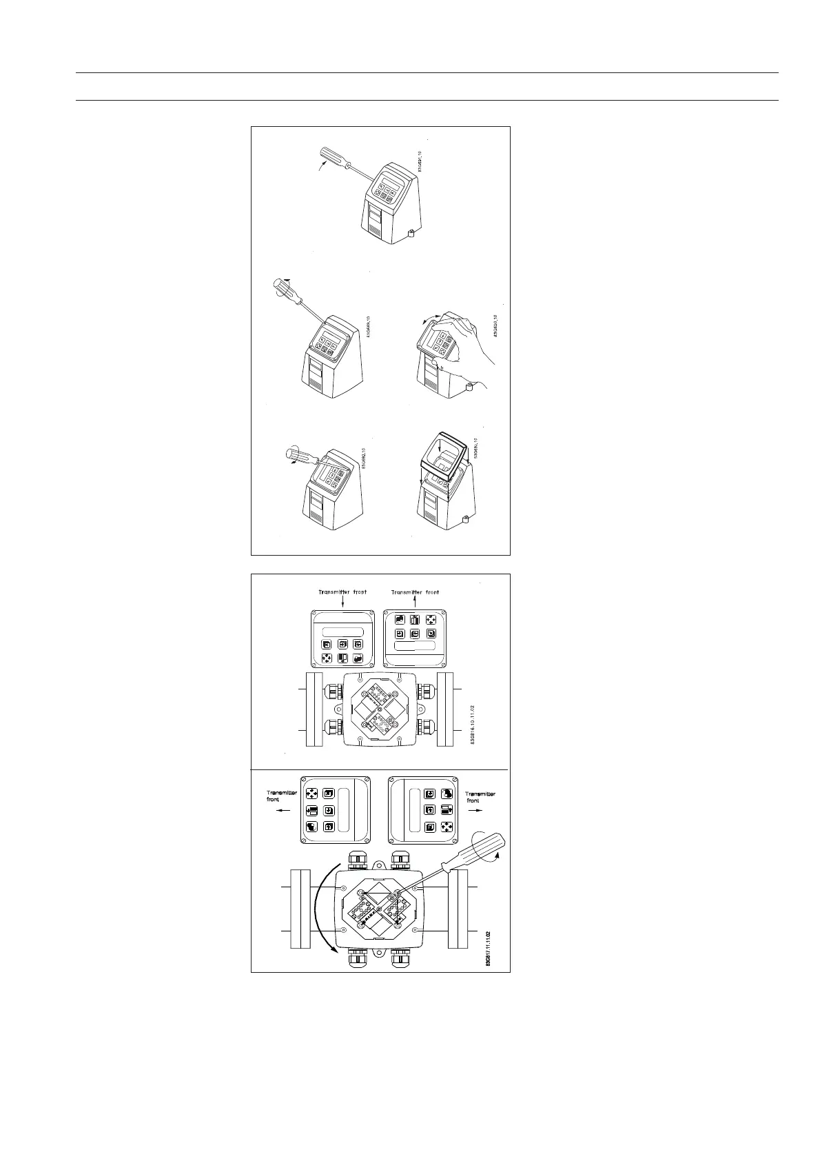
1. Use a screwdriver to remove the outer
frame.
2. Loosen the 4 screws retaining the control
pad.
3. Withdraw the control pad and turn it to the
required orientation.
4. Tighten the 4 screws until a mechanical
stop is felt in order to obtain IP 67 enclo-
sure rating.
5. Snap-lock the outer frame onto the control
pad (click).
The transmitter can be mounted in either
direction as the arrow indicates without turning
the terminal box.
The connection board needs to be oriented
according to the display direction.
The terminal box can be rotated ±90° in order
to optimize the viewing angle of the transmitter
display/keypad:
1. Unscrew the four screws in bottom of
terminal box.
2. Turn terminal box to required position.
3. Retighten screws firmly
Turning the control pad
Turning the transmitter
1
2
4
3
5

Table of Contents

Other manuals for Siemens MAG 5000

Questions and Answers:

Question and Answer IconNeed help?

Do you have a question about the Siemens MAG 5000 and is the answer not in the manual?

Siemens MAG 5000 Specifications

General IconGeneral
TypeElectromagnetic Flowmeter
Protection ClassIP67
MaterialStainless Steel, Carbon Steel
Power Supply24 V DC, 100-240 V AC
Accuracy±0.2% of flow rate
CommunicationHART, PROFIBUS, Modbus
Enclosure RatingIP67
Ambient Temperature Range-20°C to +60°C
SizesDN 2 to DN 3000
Lining MaterialsPTFE, Hard Rubber
Electrode MaterialsStainless Steel, Hastelloy, Tantalum
Process Temperature-40 to +180 °C (-40 to +356 °F) depending on liner
Process PressureUp to 40 bar (580 psi)
ApprovalsATEX, FM, CSA, IECEx
Flow Velocity Range0 to 12 m/s
Output Signals4-20 mA, Pulse, Frequency

Related product manuals