SITRANS F M
6. Installation of transmitter
49
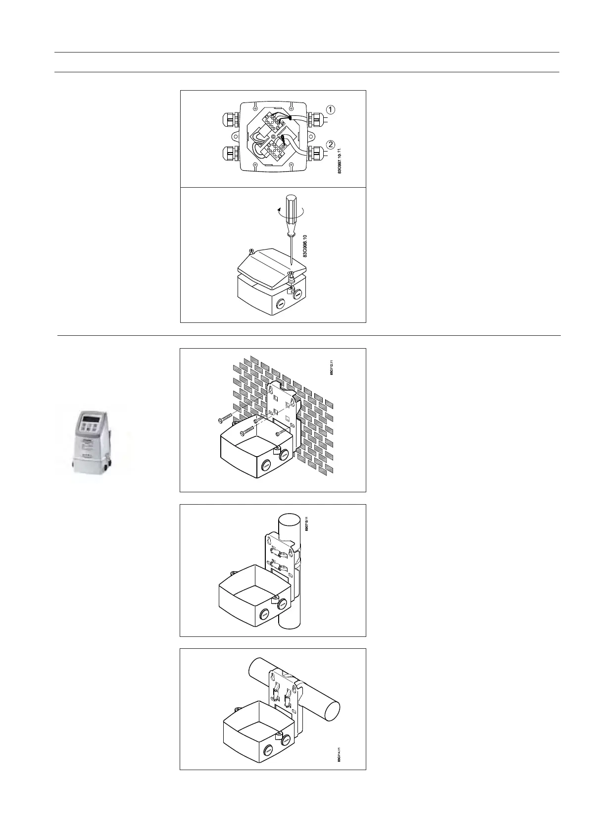
6.2.2
Remote installation -
At the sensor
Step 3
Fit the ½”NPT or M20 cable glands for the
supply and output cables.
Fit and connect the electrode and coil cables as
shown in chapter 7 “Electrical connections”.
The unscreened cable ends must be kept as
short as possible.
The electrode cable and the coil cable must be
kept separate to prevent interference.
Tighten the cable glands well to obtain
optimum sealing.
Step 4
Mount the lid on the terminal box.
6.2.3
Remote installation -
Wall mounting
MAG 6000
Mount wall bracket on a wall or into the back of
a panel.
Mount wall bracket on a vertical or horizontal
pipe using an ordinary hose clip or a duct strap.
Vertical pipe mounting
Horizontal pipe mounting
 Loading...


