24
SITRANS F M
3. Project guidance
Flow velocity
3. Project guidance
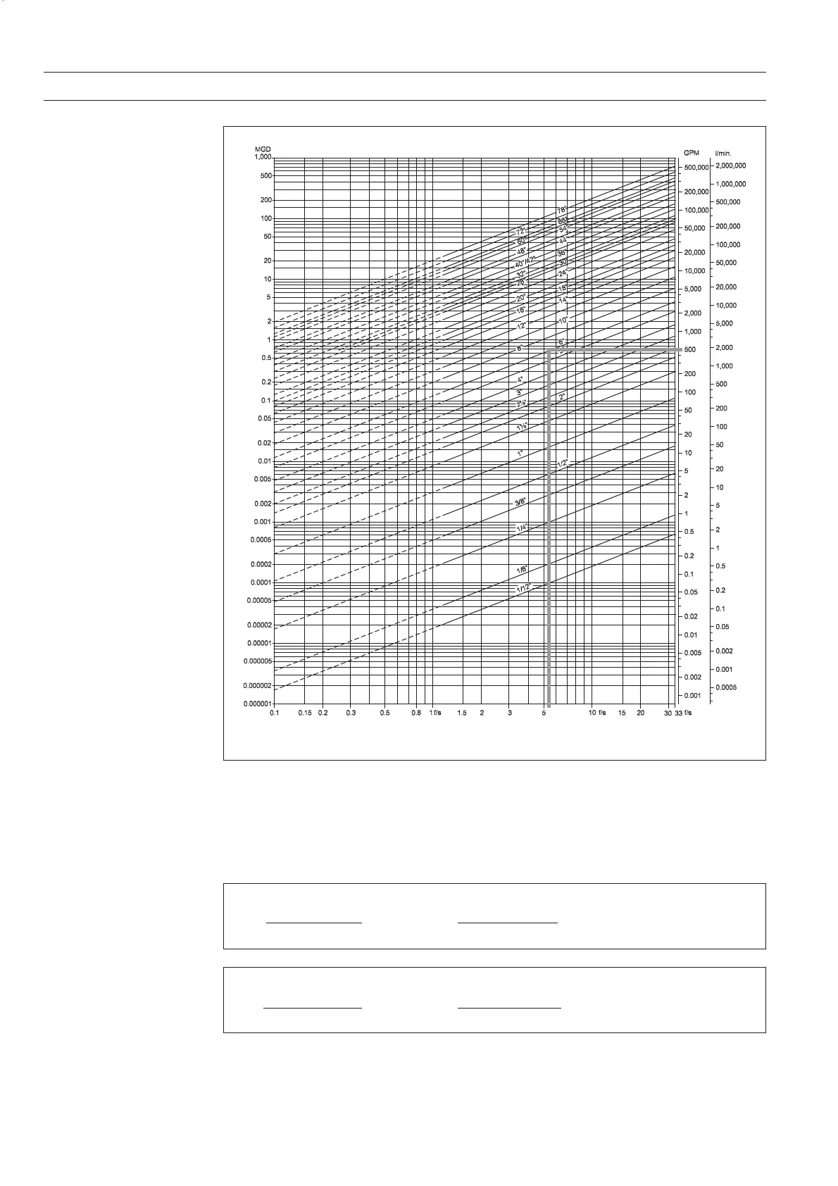
3.1.2.
Sizing table
(
1
/
12
... 78")
The table shows the relationship between flow velocity v, flow quantity Q and sensor dimension DN.
Guidelines for selection of sensor
Min. measuring range: (0 ... 0.8 ft./sec)
Max. measuring range: (0 ... 33 ft./sec)
Normally the sensor size is selected so that the nominal flow velocity v lies within the measuring
range (1 ... 15 ft./sec.)
Flow velocity calculation formula:
V =
1273.24 x Q [l/s]
[m/s] or
DN
2
[mm]
Flow velocity calculation formula:
V =
0.408 x Q [GPM]
[ft/s] or
(Pipe ID)
2
[inch]
V =
283.67 x Q [MGD]
[ft/s]
(Pipe ID)
2
[inch]
V =
353.68 x Q [m
3
/h]
[m/s]
DN
2
[mm]
 Loading...


