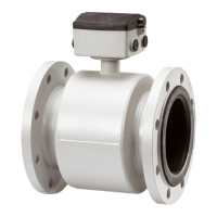
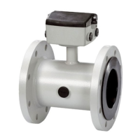
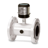
3
SITRANS F M
1.1 Product introduction ................................................................................................................................................. 5
1.2 Mode of operation .................................................................................................................................................... 6
1.3 Pressure Equipment Directive 97/23ECs ................................................................................................................. 7
1.3.1 Exclusions ............................................................................................................................................................... 8
1.3.2 Product marking ....................................................................................................................................................... 8
2.1 Sensor MAG 1100 .................................................................................................................................................... 9
2.2 Sensor MAG 1100 F ............................................................................................................................................... 11
2.3 Sensor MAG 3100 .................................................................................................................................................. 13
2.4 Sensor MAG 5100 W ............................................................................................................................................. 16
2.5.1 Transmitter MAG 5000 ........................................................................................................................................... 17
2.5.2 Transmitter MAG 6000 ........................................................................................................................................... 14
2.5.4 Safety barrier (e ia) ................................................................................................................................................ 19
2.5.5 Cleaning unit .......................................................................................................................................................... 19
2.6 Meter uncertainty ................................................................................................................................................... 20
2.7 Output characteristics MAG 5000 and MAG 6000 ................................................................................................. 21
2.8.1 Conductivity of medium and sensor cables ........................................................................................................... 22
2.8.2 Cable requirements ................................................................................................................................................ 22
2.9 Cable data (Supplied by Siemens Flow Instruments) ............................................................................................ 22
3.1.1 Sizing table (DN 2 to DN 2000) .............................................................................................................................. 23
3.1.2 Sizing table (
1
/
12
... 78") .......................................................................................................................................... 24
3.2.1 Minimum conductivity ............................................................................................................................................. 25
3.2.2 Liner selection guide .............................................................................................................................................. 25
3.2.3 Electrode selection guide ...................................................................................................................................... 25
3.3 Installation conditions ............................................................................................................................................ 25
3.4 Cleaning unit .......................................................................................................................................................... 29
3.5 Custody transfer approval ..................................................................................................................................... 30
3.6 Transmitter MAG 5000 CT, MAG 6000 CT Sealing .................................................................................................. 30
3.7 Ex survey according to Directive 94/9/EC (ATEX) ................................................................................................. 31
3.8 Approvals ............................................................................................................................................................... 32
4.1 Sensor MAG 1100 .................................................................................................................................................. 33
4.2 Sensor MAG 1100 F ............................................................................................................................................... 34
4.3 Sensor MAG 5100 W ............................................................................................................................................. 37
4.4 Sensor MAG 3100 .................................................................................................................................................. 39
4.4.1 Sensor MAG 3100 .................................................................................................................................................. 39
4.5 Transmitter ............................................................................................................................................................. 41
5.1 Potential equalization ............................................................................................................................................. 44
5.2 Inlet protection MAG 3100 ..................................................................................................................................... 45
5.3 Cathodic protected piping ...................................................................................................................................... 45
6.1 Compact installation MAG 5000 and MAG 6000 .................................................................................................... 46
6.2.1 Add-on modules MAG 6000 only ............................................................................................................................ 48
6.2.2 Remote installation. At the sensor ......................................................................................................................... 49
6.2.3 Remote installation. Wall mounting ......................................................................................................................... 50
6.2.4 Remote installation. Transmitter in 19" insert ......................................................................................................... 51
6.2.5 Add-on modules MAG 6000 only ............................................................................................................................ 52
6.2.6 Installation in IP 66 wall mounting enclosure ......................................................................................................... 53
6.2.7 Installation in IP 65 panel mounting enclosure (front of panel) .............................................................................. 54
6.2.8 Installation into the back of a panel ...................................................................................................................... 55
6.3 Transmitter Safety barrier ...................................................................................................................................... 56
6.4 Transmitter Cleaning unit ........................................................................................................................................ 57
7.1 Transmitter MAG 5000 and MAG 6000 connection diagram ................................................................................... 58
7.2 Wiring diagram for transmitter and sensor ............................................................................................................. 59
8.1 Keypad and display layout ..................................................................................................................................... 62
8.2 Menu build-up ......................................................................................................................................................... 63
8.2.1 Password ............................................................................................................................................................... 63
8.3.1 MAG 5000 and MAG 6000 - Menu overview .......................................................................................................... 64
8.3.2 MAG 5000 CT and MAG 6000 CT - Menu overview ................................................................................................ 65
8.4.1 Basic settings ........................................................................................................................................................ 66
8.4.2 Outputs .................................................................................................................................................................. 67
8.4.3
Digital and relay outputs ........................................................................................................................................ 67
8.4.4 Relay outputs ......................................................................................................................................................... 68
8.4.5 External input ......................................................................................................................................................... 68
8.4.6 Sensor characteristics ........................................................................................................................................... 69
8.4.7 Reset mode ............................................................................................................................................................ 69
8.4.8 Service mode ......................................................................................................................................................... 70
8.4.9 Operator menu setup ............................................................................................................................................. 71
8.4.10 Product identity ..................................................................................................................................................... 72
8.4.11 Change password .................................................................................................................................................. 72
8.4.12 Language mode ..................................................................................................................................................... 73
8.4.13 HART
®
communication MAG 5000 HART or as add-on module .............................................................................. 73
8.5.1 Flow rate ................................................................................................................................................................ 74
8.5.2 Totalizer ................................................................................................................................................................. 74
8.5.3 Batch ..................................................................................................................................................................... 74
8.6.1 Settings available .................................................................................................................................................. 75
8.6.2 Dimension dependent factory settings .................................................................................................................. 76
8.6.3 Dimension dependent batch and pulse output settings ......................................................................................... 76
8.6.4 MAG 5000 CT and MAG 6000 CT settings ............................................................................................................. 80
8.7.1 Error handling ......................................................................................................................................................... 81
8.7.2 List of error numbers ............................................................................................................................................. 82
9.1 Transmitter check list ............................................................................................................................................. 83
9.2 Trouble shooting MAG transmitter .......................................................................................................................... 84
9.3 Check list MAG sensor .......................................................................................................................................... 85
9.4 Coil resistance table .............................................................................................................................................. 86
10. Ordering ................................................................................................................................................................. 87
2. Technical data
1. Product introduction
3. Project guidance
4. Dimensions and wei ght
6. Installation of transmitter
5. Installation of sensor
7. Electrical connection
8. Commissioning
10. Ordering
9. Service

 Loading...


