Configuration and Connection Examples 12.2010
6SE7087-6QX70 (Version AM) Siemens AG
2-28 Compendium Motion Control SIMOVERT MASTERDRIVES
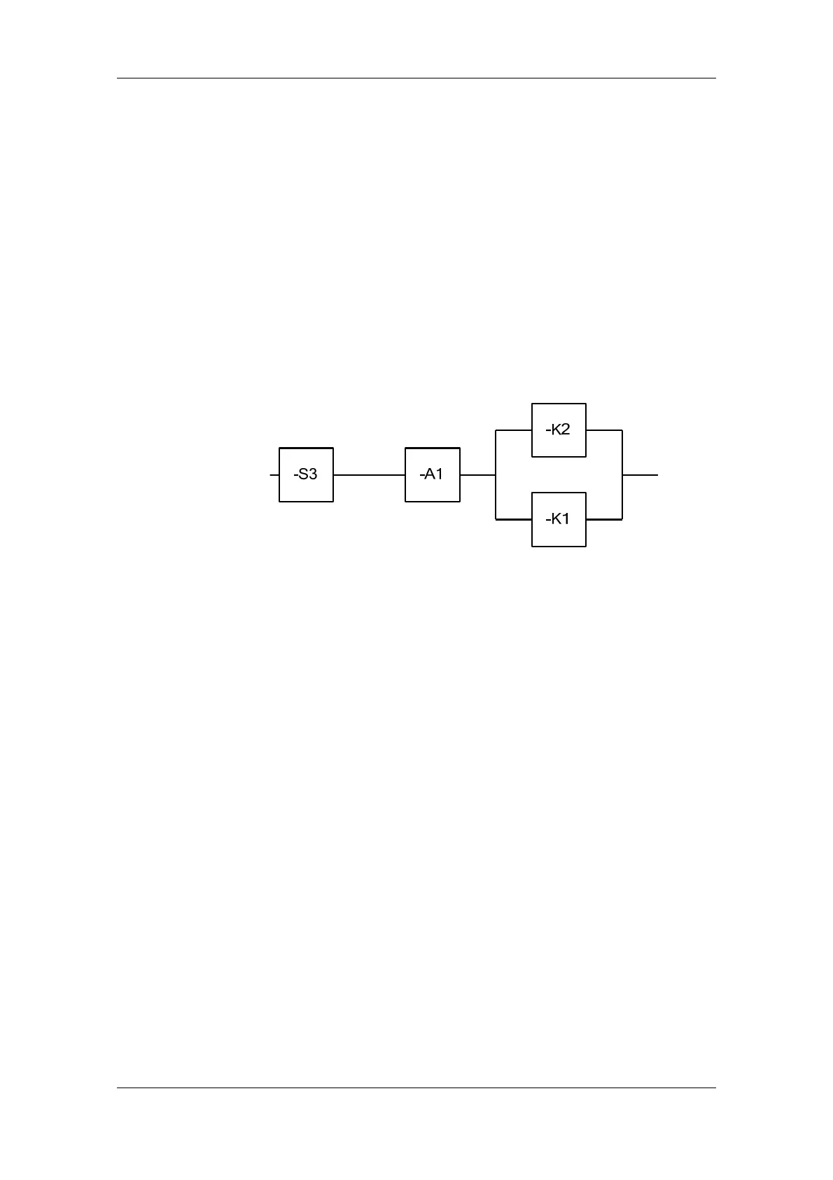
♦ The contacts of the safety switching device –A1 are opened.
♦ The safety relay –K1 and the line contactor –K2 are de-energized.
(The NO contacts drop out and the motor is separated in two
channels from the torque-producing power supply.)
This behavior is identical to Stop Category 0 in accordance with
EN 60204-1:2006 /R9/.
♦ Pulse suppression before the drive has reached standstill causes
the motor to coast down. Vertical axes must be secured by holding
brakes or similar.
♦ The slide switch of –A1 must be in the "Monitored" position for this
application.
Fig. 2-12 Block diagram of the supplementary safety function Emergency Stop
Emergency Stop
actuation
Observations
 Loading...


