08.2012 Technology Option F01
Siemens AG 6SE7087-6QX70 (Version AN)
SIMOVERT MASTERDRIVES Compendium Motion Control 9-45
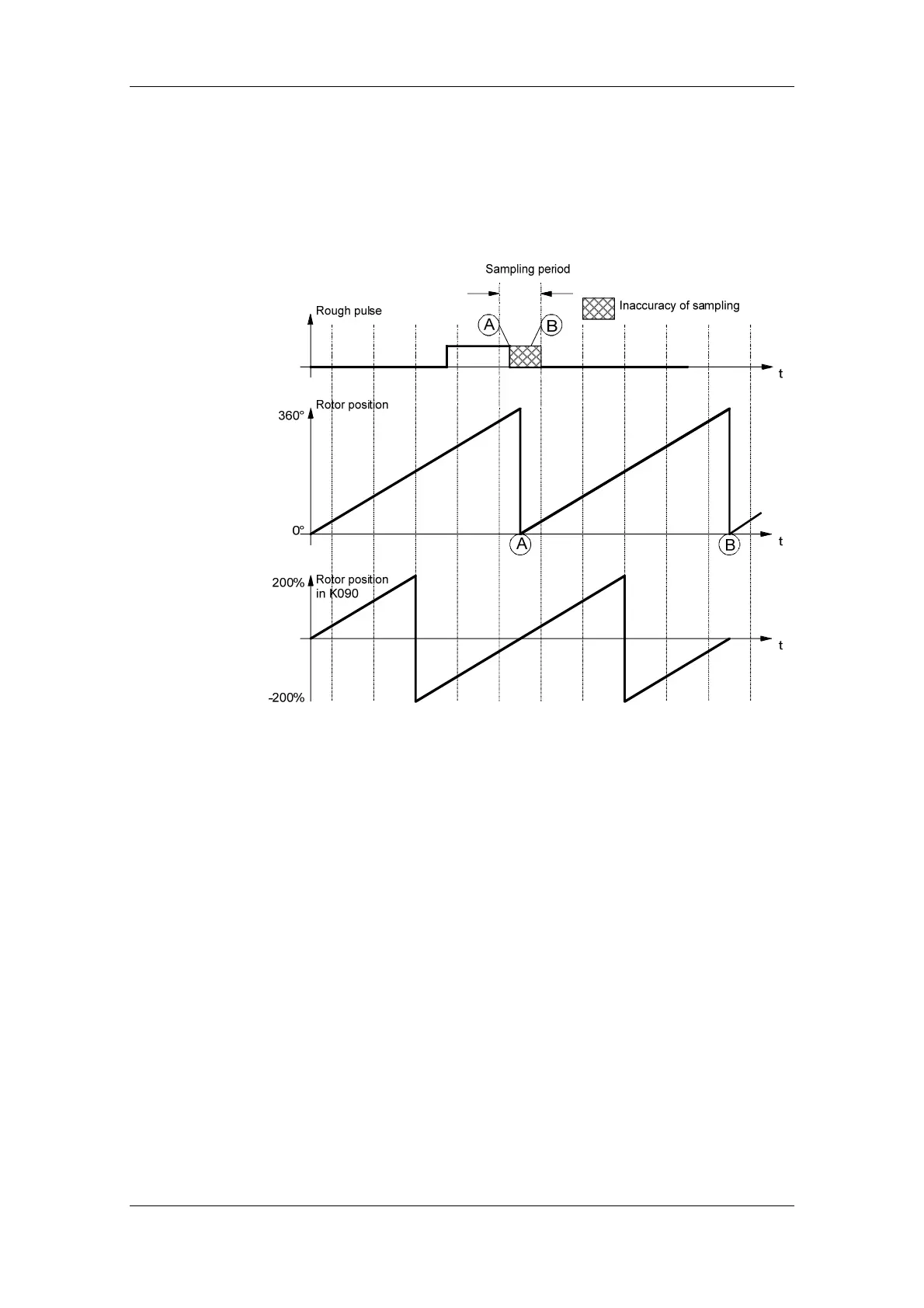
Since the rough pulse is read in via a digital input, the signal is
evaluated in the sampling time of the digital inputs. If the negative edge
of the rough pulse is located directly above the rotor zero position, the
detection of the home position may be incorrect, because the signal is
detected with the inaccuracy of a sampling period.
Example:
Fig. 9-20
In the configuration shown in the graphic, the negative edge of the
rough signal can be detected in front of the rotor zero position (sample
A), resulting in the detection of the home position at point A. If the
negative edge is not detected until after the rotor zero position (sample
B), the home position is located at point B.
To prevent incorrect detection of the home position, the proximity
switch must be aligned such that the falling edge does not coincide with
the rotor zero, but occurs in the most central position possible between
two rotor zero crossings. The rotor zero position can be monitored in
KK090 (e.g. using display parameter r033.1, if P032.1 = 90 is set
[30.2]).
Proximity switch
alignment
 Loading...


