08.2012 Technology Option F01
Siemens AG 6SE7087-6QX70 (Version AN)
SIMOVERT MASTERDRIVES Compendium Motion Control 9-81
The following rules must be followed during configuration:
♦ One of the axes is defined as the master drive.
♦ The master drive must also be the SIMOLINK master (dispatcher).
The module address is zero.
♦ The virtual master axis is enabled [832] on the master drive.
♦ All drives, including the master drive, move in synchronism with the
virtual master axis [832].
♦ The output of the virtual master axis is wired to the SIMOLINK send
block [160].
♦ The input of the synchronization block is connected to the receive
block of the SIMOLINK,
including for the master drive.
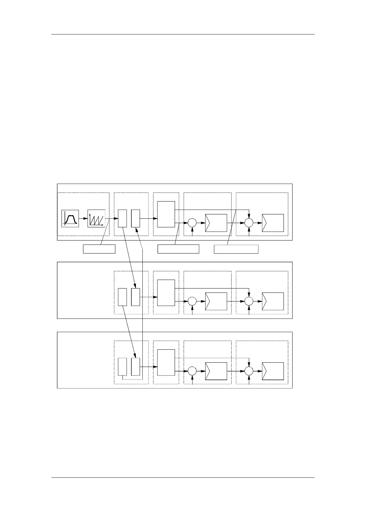
The graphic below illustrates the path of the master value of the virtual
master axis, and the controller structure.
SEND
REC
Virtual master axis
SIMOLINK
Synchronization
Master drive
Slave drive 1
Slave drive 2
Master value
SYNC
Position controller
s n
Speed controller
REC
SIMOLINK
Synchronization
SYNC
Position controller
s n
REC
SIMOLINK Synchronization
SYNC
Position controller
s n
Speed precontrol
Position setpoint
SENDSEND
Speed controller
Speed controller
Fig. 9-32
 Loading...


