08.2012 Technology Option F01
Siemens AG 6SE7087-6QX70 (Version AN)
SIMOVERT MASTERDRIVES Compendium Motion Control 9-97
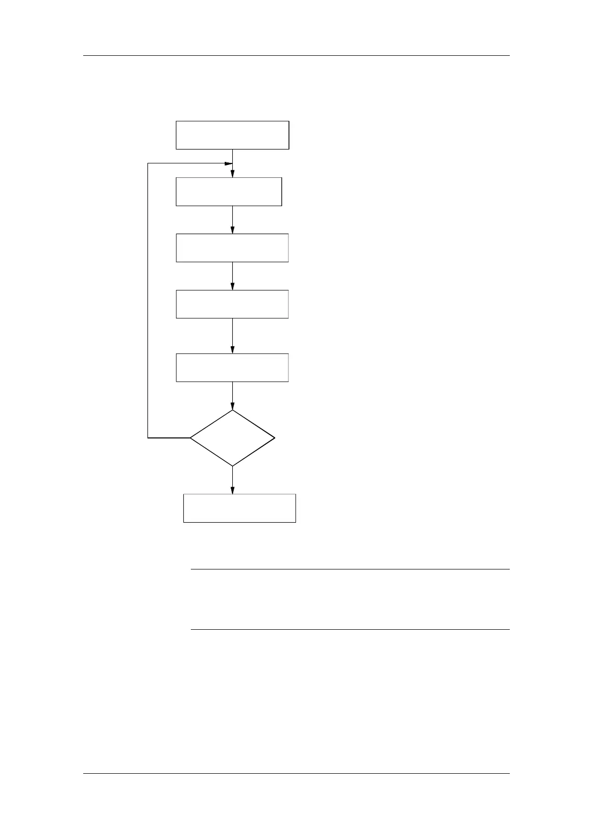
The following sequence must be followed when entering the cam:
Selection of table
configuration
Number of
interpolation points
Table width
Check table
U615 = Table configuration
0 = 1 table with 400 interpolation points
1 = 2 tables with 200 interpolation points each
2 = 4 tables with 100 interpolation points each
3 = 8 tables with 50 interpolation points each
4 = max. eight tables with
a total of 400 interpolation points
U629 Number of interpolation points
Indices 1...8 for tables 1...8
U620 Table widths of tables
Indices 1...8 for tables 1...8
U617 = 2: Check table
Indices 1...8 for tables 1..8
U617.x = 0 ?
No, then table is errored
Error status in n668 [839.1]
Yes, then table is checked
and valid
Table o.k.
Enter table interpolation
points
Depending on table configuration
U630 ... U648
Interpolation point = X axis
Interpolation value = Y axis
Fig. 9-42
The interpolation points (x coordinates) must be defined in ascending
order.
Only interpolation points within the range from 0 to the table width are
allowed.
Interlocks in tables:
An active table cannot be changed at all. Except for table width and
number of interpolation points, an inactive table can be changed,
checked and accepted as a background function. The operating mode
must otherwise be switched over to 1:1 or gearbox.
Table input / table
check
NOTE
 Loading...


