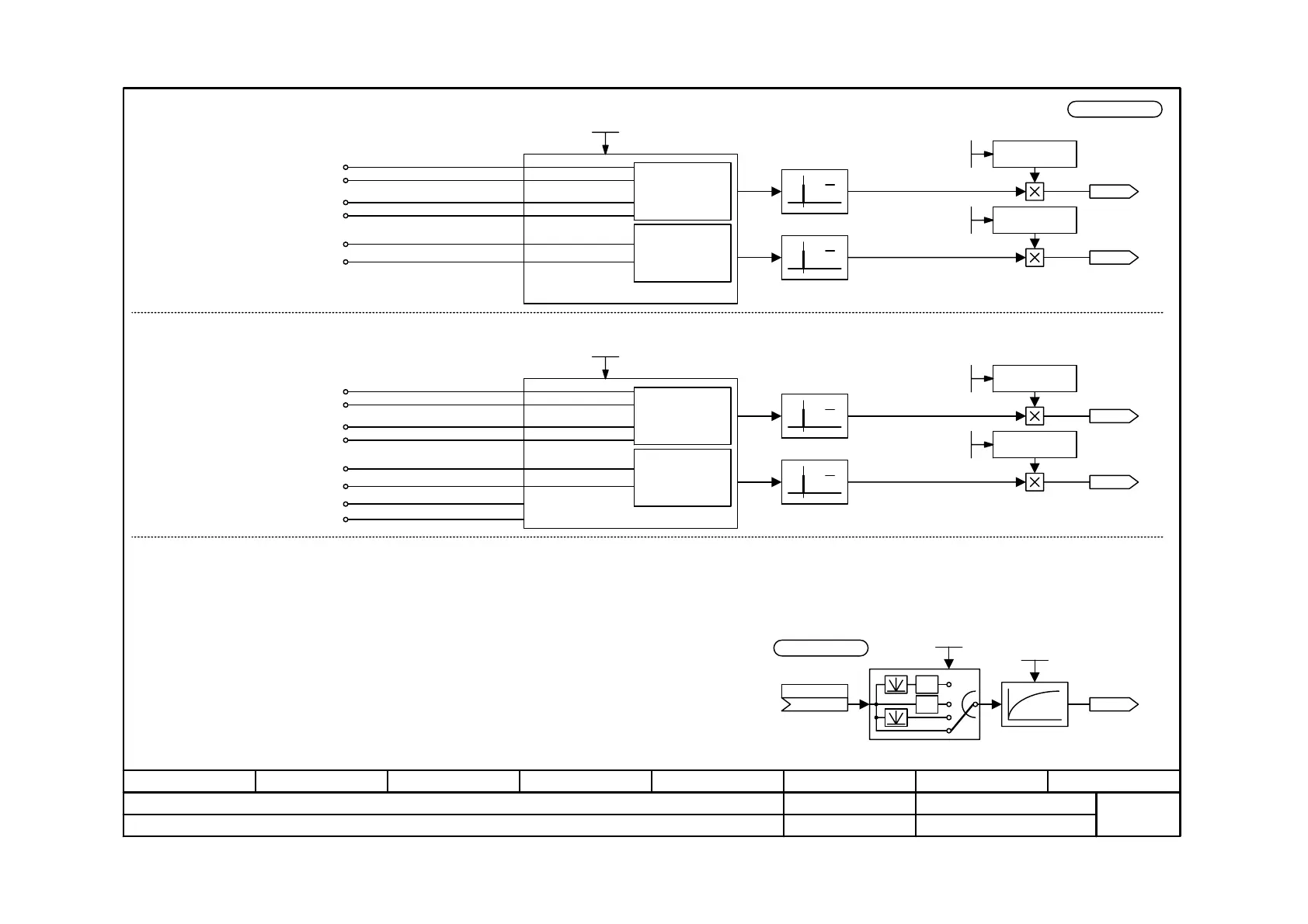
Function diagram
87654321
fp_mc_256_e.vsd
Setpoint input
MASTERDRIVES MC
07.01.02
Setpoint input via external frequency or encoder signals with the SBP optional board
-256 -
V2.5
Frequency signal evaluation mode
(P139 = 1xxx)
Terminal assignment X400:
60...67: n.c.
Terminal assignment X401: <1>
68: Forward counter channel 1+
69: Forwards counter channel 1-
70: Reverse counter channel 1+
71: Reverse counter channel 1-
72: Forwards counter channel 2+
73: Forwards counter channel 2-
74: n.c.
75: n.c.
Counter
channel 1
(forw./rev.)
Counter
channel 2
(forwards)
SBP
Channel 1 forwards counter (+)
Channel 1 forwards counter (-)
Channel 1 reverse counter (+)
Channel 1 reverse counter (-)
Channel 2 forwards counter (+)
Channel 2 forwards counter (-)
<3>
Terminal assignment X400:
60: Supply voltage
61: Supply ground
62...67: n.c.
Terminal assignment X401: <4>
68: Track A+ (channel 1)
69: Track A- (channell 1)
70: Track B+ (channel 1)
71: Track B- (channel 1)
72: Forwards counter channel 2+
73: Forwards counter channel 2-
74: n.c.
75: n.c.
Counter
channel 1
(forw./rev.)
Counter
channel 2
(forwards)
SBP
TrackA (+)
Track A (-)
Track B (+)
Track B (-)
Channel 2 forwards counter (+)
Channel 2 forwards counter (-)
Encoder signal evaluation mode
(P139 = 2xxx)
Normalization via
- Frequency signal evaluation mode
Frequency (frequencies stated in P141.1 and .2
correspond to the output of
100% to the connectors KK0094 and KK0095.
- Encoder signal evaluation mode
Pulse number (pulse numbers of connected
encoders stated in P140.1 and .2)
The reference value is P353.1
maximum input frequency: 1 MHz
Setting P139:
Input level A/B track
xxx0: Channel 1 / encoder input HTL unipolar
xxx1: Channel 1 / encoder input TTL unipolar
xxx2: Channel 1 / encoder input HTL differential input
xxx3: Channel 1 / encoder input TTL / RS422
Input level zero track
xx0x: Channel 2 HTL unipolar
xx1x: Channel 2 TTL unipolar
xx2x: Channel 2 HTL differential input
xx3x: Channel 2 TTL / RS422
Encoder power supply
X0XX: 5 V
X1XX: 15 V
Mode of setpoint evaluation
0xxx: Frequency signal evaluation deactivated
1xxx: Frequency signal evaluation mode
2xxx: Encoder signal evaluation mode
Supply voltage
Supply ground
<3> optional smoothing s. Function Diagram 735:
d
dt
d
dt
Normalization
<2>
d
dt
d
dt
X401/73
X401/72
X401/71
X401/70
X401/69
X401/68
X401/68
X401/69
X401/70
X401/71
X401/72
X401/73
X400/60
X400/61
<3>
Normalization
<2>
<1>
<2>
<3>
Normalization
<2>
<3>
Normalization
<2>
-1
-1
3
2
1
0
U12x (0)
0...3
K
U1xx (0)
Smoothing Time Constant
0...10000 ms
U1xx (0)
Kxxxx
maximum input frequency: 410 kHz<4>
n959.33 = 4
KK0094
SBP Setpoint Channel 1
KK0095
SBP Setpoint Channel 2
Conf Setp Enc
1000...1133
P139 (0000)
Conf Setp Enc
2000...2133
P139 (0000)
SetpEnc Ref Freq
500...1000000 Hz
P141.1 (10000)
SetpEnc Ref Freq
500...1000000 Hz
P141.2 (10000)
KK0094
SBP Setpoint Channel 1
KK0095
SBP Setpoint Channel 2
SetpEncPulse #
60...20000
P140.1 (1024)
SetpEncPulse #
60..20000
P140.2 (1024)
U952.07__ (20)
 Loading...


