Meaning of the axes
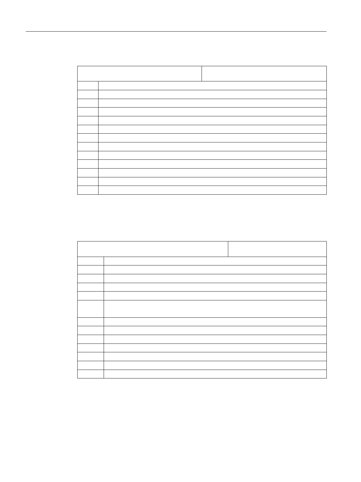
MD52206 $MCS_AXIS_USAGE[n] Meaning of the axes in the channel
[n] channel axis number
= 0 No special meaning
= 1 Tool spindle (rotating tool)
= 2 Auxiliary spindle (rotating tool)
= 3 Main spindle (turning)
= 4 Separate C axis of the main spindle (turning)
= 5 Counterspindle (turning)
= 6 Separate C axis of the counterspindle (turning)
= 7 Linear axis of the counterspindle (turning)
= 8 Tailstock (turning)
= 9 Steady (turning)
= 10 B axis (turning)
= 12 B axis in counterspindle (turning)
= 13 Transverse travel X of the counterspindle (turning)
Defining the direction of rotation
Enter the direction of rotation for the rotary axes that are not configured in a tool holder or a 5-
axis transformation via the following channel-specific machine data.
MD52207 $MCS_USAGE_ATTRIB[n] Attribute of the axes in the channel
[n] channel axis number
Bit 0 Rotates around 1st geometry axis (for rotation axis)
Bit 1 Rotates around 2nd geometry axis (for rotation axis)
Bit 2 Rotates around 3rd geometry axis (for rotation axis)
Bit 3 Direction of rotation is counter-clockwise (for rotary axis / C axis).
Bit 4 Displayed direction of rotation of the spindle/C axis for the M function M3 is counter-clockwise
Bit 5 Inverts M3 / M4 (for spindles)
This bit must be set analogous to PLC bit DB31, ... DBX17.6!
Bit 6 Display rotary axis as offset target for measurement
Bit 7 List rotary axis in the position pattern
Bit 8 List rotary axis to accept blank (on milling machines)
Bit 9 Spindle is not SPOS-capable
Bit 10 Rotary axis rotates around 1st geometry axis (only for position pattern)
Bit 11 Rotary axis rotates around 2nd geometry axis (only for position pattern)
Bit 12 Rotary axis rotates around 3rd geometry axis (only for position pattern)
Technologies and cycles
21.1 Activating turning/milling/drilling/grinding technologies
SINUMERIK Operate (IM9)
506 Commissioning Manual, 12/2017, 6FC5397-1DP40-6BA1
 Loading...


