Axis configuration
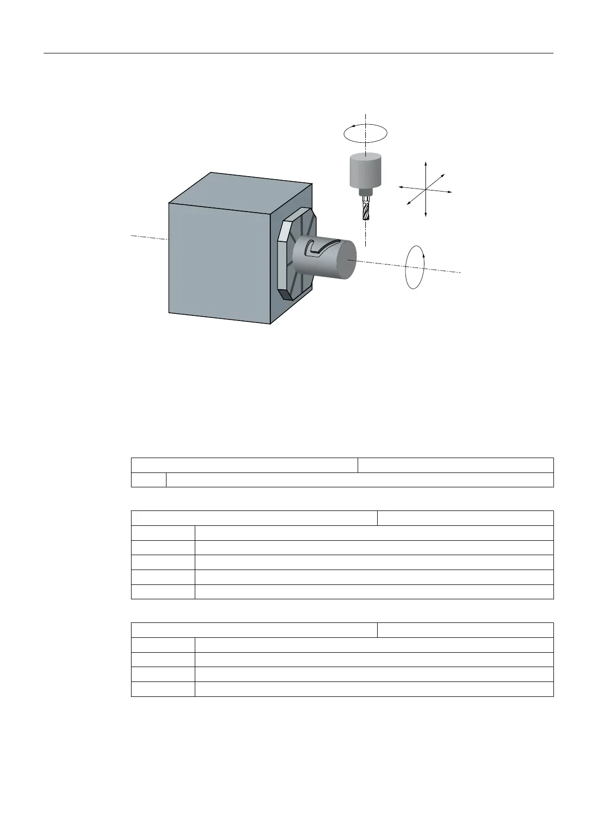
X 1st axis of the machining plane parallel to the rotary axis
Y 2nd axis of the machining plane
Z Infeed axis (tool axis) perpendicular (radial) to the rotary axis
A Rotary axis
C Working spindle
Figure 21-2 Machining slots on a cylinder surface with X-A-Z kinematics
You must configure two data sets with the following machine data for the machine illustrated
above:
MD20070 $MC_AXCONF_MACHAX_USED[4] Machine axis number valid in channel
= 5 Number of channel axes
MD20080 $MC_AXCONF_CHANAX_NAME_TAB[ ] Name of channel axis in the channel
[0] = XC Channel axis XC, corresponds to channel axis 1
[1] = YC Channel axis YC, corresponds to channel axis 2
[2] = ZC Channel axis ZC, corresponds to channel axis 3
[3] = A Channel axis A, corresponds to channel axis 4
[4] = C Channel axis C, corresponds to channel axis 5
MD28082 $MC_MM_SYSTEMFRAME_MASK System frames (SRAM)
= 21H Default setting
Bit 0 = 1 System frame for actual value setting and scratching
Bit 5 = 1 System frame for cycles
Bit 6 = 1 System frame for transformations
Technologies and cycles
21.4 Milling
SINUMERIK Operate (IM9)
524 Commissioning Manual, 12/2017, 6FC5397-1DP40-6BA1
 Loading...


