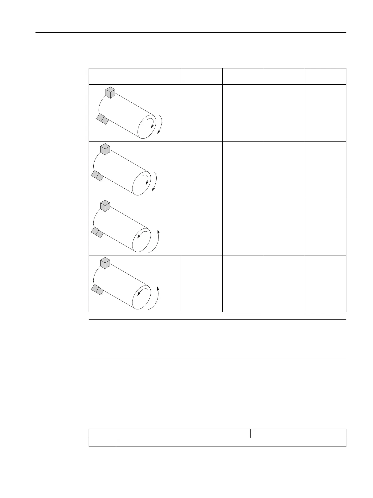
As a result, the following setting options are obtained for the main spindle:
Main spindle direction of rotation 52207[n]
bit 3 =
52207[n]
bit 4 = *)
52207[n]
bit 5 =
DB31, ...
DBX17.6
0
0
0
0
0
1
1
1
1
1
0
0
1
0
1
1
Note
MD52207[n] bit 4 = *)
Bit 4 can be set from the operator's view (values as specified) or according to DIN ("0" and "1"
are then interchanged).
Dimensions
To define the reference point for moving the counterspindle, you must first communicate the
dimensions of the counterspindle. You can either enter the dimensions in the following axis-
specific cycle machine data or in menu "Parameter" → "Setting data" → "Spindle chuck data".
Changes to the machine data are automatically accepted in the menu and vice versa.
MD53240 $MAS_SPINDLE_PARAMETER[ ] Spindle chuck data
[0] Chuck dimensions
Technologies and cycles
21.5 Turning
SINUMERIK Operate (IM9)
Commissioning Manual, 12/2017, 6FC5397-1DP40-6BA1 531
 Loading...


