EXAMPLE of Placeholder Characters:
Example 1:
•
binary 00000000.00000000.00000000.00101011 is not permitted
•
binary 00000000.00000000.00000000.00111111 is permitted
Example 2:
•
The PDC IP address is: 192.172.16.1
•
Placeholder: 0.0.0.127
The device accepts requests within the IP address range of 192.172.16.1 to 192.172.16.127.
Example 3:
•
The PDC IP address is: 192.172.16.100
•
Placeholder: 0.0.0.3
The device accepts requests within the IP address range of 192.172.16.100 to 192.172.16.103.
If a PDC attempts to establish a connection to the device, the PDC IP addresses and corresponding place-
holders are checked in the same order as they had been configured (IP address PDC1, IP address PDC2,
IP address PDC3). Running through the list is stopped with the first match of the IP address, placeholder and
requested IP address range and the connection is built-up. If there are no matches, the attempt to connect is
rejected.
If you have configured IP address 0.0.0.0 and the placeholder 255.255.255.255, every IP address received is
accepted as valid. This could be of use in the course of commissioning measures.
NOTE
You must have configured at least 1 IP address in order to establish a connection between the device and
PDC.
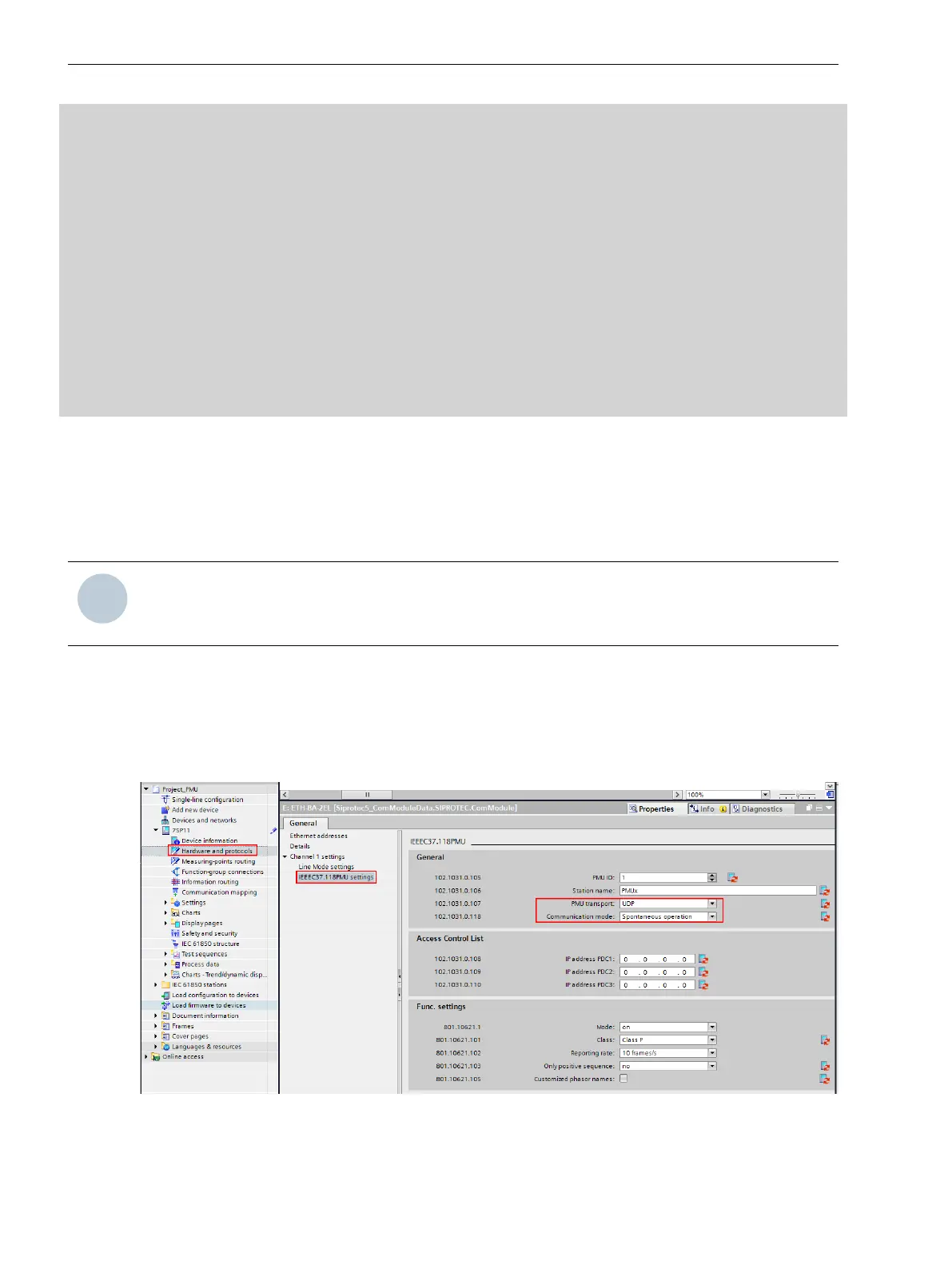
If you use the asynchronous data transmission method, set the PMU transfer parameter to UDP and the
Communication mode parameter to Spontaneous operation. The PMU data are then sent cyclically via
UDP to each PDC/IP address permanently configured in DIGSI. You may not configure placeholders for PDC/IP-
address ranges in this communication mode.
Data output starts immediately after the device has booted. In this way, no starting signal from the PDC is
necessary to start data transmission.
[sc_spontan_pmu, 1, en_US]
Figure 6-21 PMU Configuration for Spontaneous Transmission
Function-Group Types
6.4 Function-Group Type Phasor Measurement Unit (PMU)
162 SIPROTEC 5, Fault Recorder, Manual
C53000-G5040-C018-5, Edition 11.2017

 Loading...


