Functional
Area
Brief Description Change in Load
•
FG
connec-
tions
•
Fast
GOOSE
•
Interaction between indi-
vidual function groups, for
example, between the FG
VI 3-phase and the FG
recorder
•
Fast GOOSE communica-
tion
Adding or removing
•
Recorder Functions
•
Current and voltage functions
•
Fast GOOSE connections
CFC event-trig-
gered,
standard
GOOSE
CFC charts with a maximum
processing time of 40 ms
Adding or removing CFC charts in the event-triggered
process range
•
Create CFC chart
•
Delete CFC chart
•
Change the process range in the properties of the CFC
chart
Add to or remove from CFC charts in the event-triggered
process area
•
Control
•
Other
contin-
uous
function
chart
•
Opera-
tional
measured
values
•
Control and interlocking
•
CFC charts in the area of
control, measured-value
preprocessing, and event-
controlled
•
Operational measured
values
Adding or removing
•
CFC charts in the control area
•
Operational measured values
•
CFC charts in the measured values area
If the load model displays a warning, bear in mind the following general instructions:
The areas named in the table are listed in descending order of real time requirements. If a warning appears to
the effect that the guaranteed response times may be exceeded in an area, you may be able to return to the
permitted area by taking the following measures:
•
Reduce the functional scope in the marked area (red exclamation mark)
•
Reduce the functional scope in another area with higher real time requirements
When you have reduced the application, check the display in resource consumption! If a function has been
switched off, it will continue to represent a load for the area. If you do not need the function, delete it rather
than switching it off.
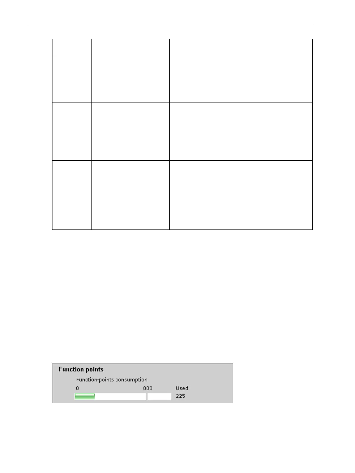
Function Points
When you order a SIPROTEC 5 device, you are also ordering a function-points account for use of additional
functions.
The following figure illustrates consumption of function points in the current application with respect to the
existing function-points account.
[scfpunkt-141210-01, 1, en_US]
Figure 8-2 Resource Overview: Function-Points Consumption
8.2.2
Supervision Functions
8.2 Resource-Consumption Supervision
364 SIPROTEC 5, Fault Recorder, Manual
C53000-G5040-C018-5, Edition 11.2017

 Loading...


