Log
For every device error with a subsequent restart (reset), only the restart can be detected in the operational log.
The actual supervision indication is entered in the device-diagnosis log at the point in time of the fault detec-
tion and before the restart. These indications are recorded with a real-time stamp and are thus available for
later analyses. The device-diagnosis log contains expanded fault descriptions. There you also receive recom-
mendations of corresponding corrective measures for each detected device error.
You can find further information on handling the logs in chapter 3.
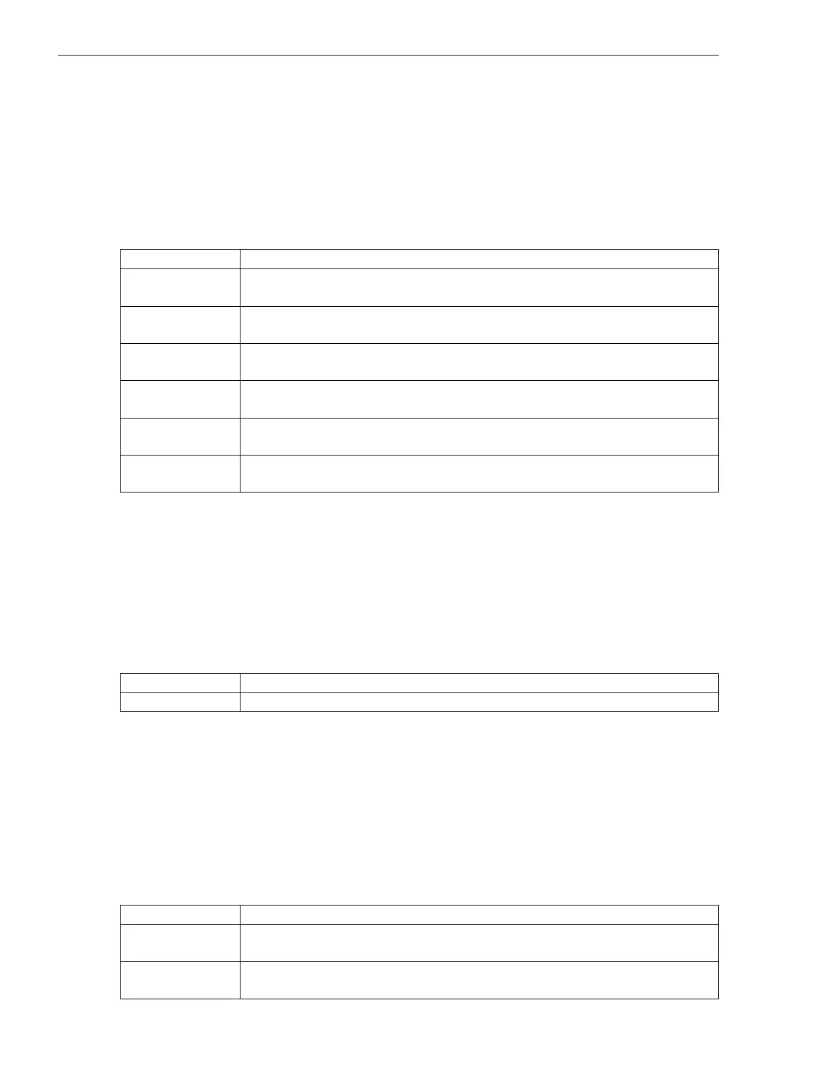
Overview of Errors
Number Device-Diagnosis Log
826 Processor error on the base module:
If the fault occurs numerous times, contact the Customer Support Center.
830 FPGA hardware error on the base module:
Contact the Customer Support Center.
834 Memory error (short term):
Reset initiated.
3823 Program run error:
If the fault occurs numerous times, contact the Customer Support Center.
826 CPU overload:
If the fault occurs numerous times, contact the Customer Support Center.
Miscellaneous Internal firmware error:
If the fault occurs numerous times, contact the Customer Support Center.
Defect Severity 3
Faults of defect severity 3 are fatal device faults that lead to device immediately going into the fallback mode.
The signal
(_:301) Device status
goes to the Alarm state. The Warning state is not supported for this
signal.
Fatal device errors are errors that cannot be resolved by a restart of the device. In this case, contact the
Customer Support Center. The device goes permanently out of operation, a failure is avoided. In the fallback
mode, minimal operation of the device via the on-site operation panel and DIGSI is possible. In this way, for
example, you can still read out information from the device-diagnosis log.
Life contact
Is terminated in the fallback mode
Red error LED Is activated in the fallback mode
Log
For every device error that immediately leads to entry into the fallback mode, entries from supervision
messages and from the signal
(_:301) Device status
into the operational log are not possible. The
actual supervision indication is entered in the device-diagnosis log at the point in time of the fault detection,
that is, before entry into the fallback mode. These indications are recorded with a real-time stamp and are thus
available for later analyses. The device-diagnosis log contains expanded fault descriptions. There, you are
offered recommendations of corresponding corrective measures for each detected device error.
You can find further information on handling the logs in chapter 3.
Overview of Errors
Number
Device-Diagnosis Log
2822 Memory error (continuous)
Contact the Customer Support Center.
4727, 5018-5028 Hardware failure at module 1-12:
Contact the Customer Support Center.
8.8.4
Supervision Functions
8.8 Error Responses and Corrective Measures
406 SIPROTEC 5, Fault Recorder, Manual
C53000-G5040-C018-5, Edition 11.2017

 Loading...


