EasyManuals Logo

Siemens SIPROTEC 5 User Manual

Siemens SIPROTEC 5
490 pages
To Next Page IconTo Next Page
To Previous Page IconTo Previous Page
Page #206 background imageLoading...
Page #206 background image
No. Information Data Class
(Type)
Type
_:11611:60 Sensor 12:Failure SPS O
_:11611:80 Sensor 12:TmpOut MV O
Communication with RTD Unit
Integration of a Serial RTD Unit (Ziehl TR1200)
Connection of the Communication Lines
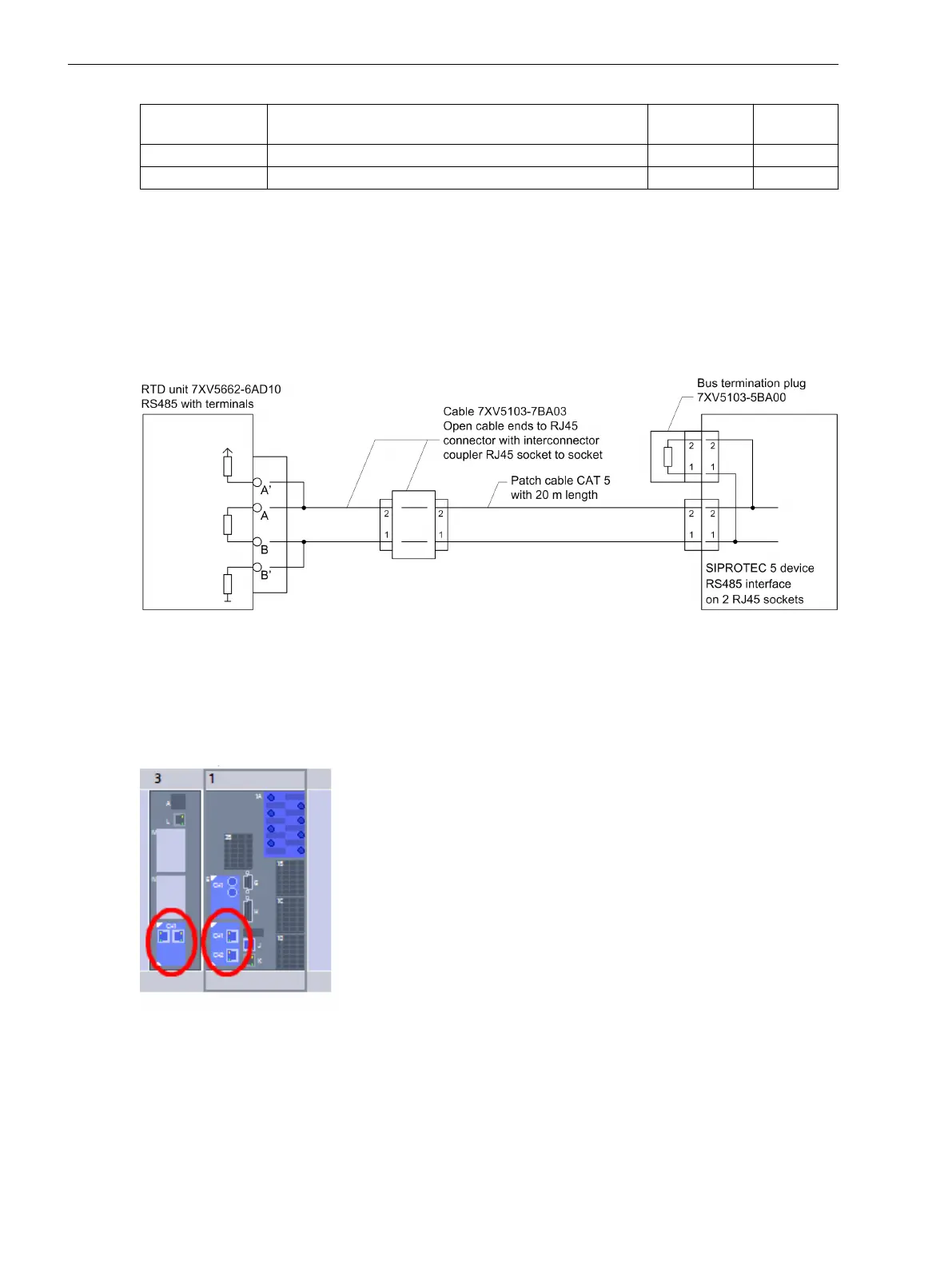
Figure 6-60 shows how you connect the RTD box to the SIPROTEC 5 device. Note that Pin 1 of the RJ45 plug is
connected to RTD-B and Pin 2 is connected to RTD-A.
[dwverbau-201112-01.tif, 1, en_US]
Figure 6-60 Connection of the RTD Unit to the SIPROTEC 5 Device
Adding a USART Module
Add a USART-AB-1EL or a USART-AC-2EL USART module in DIGSI to the device. The USART module must be
inserted at one of the plug-in positions for communication modules in the base module or in the CB202
expansion module (refer to the following figure).
[scauser3-190214-01, 1, en_US]
Figure 6-61 Insertion Position for a USART Module
Selecting the SUP Protocol
Select the Slave Unit Protocol (SUP). This protocol is responsible for the communication between the SIPROTEC
5 device and the RTD Unit.
6.5.9
6.5.9.1
Function-Group Types
6.5 Function-Group Type Analog Units
206 SIPROTEC 5, Fault Recorder, Manual
C53000-G5040-C018-5, Edition 11.2017

Table of Contents

Other manuals for Siemens SIPROTEC 5

Questions and Answers:

Question and Answer IconNeed help?

Do you have a question about the Siemens SIPROTEC 5 and is the answer not in the manual?

Siemens SIPROTEC 5 Specifications

General IconGeneral
SeriesSIPROTEC 5
Communication ProtocolsIEC 61850, DNP3, Modbus
CybersecurityRole-based access control, secure communication
Modular DesignYes
Hardware RedundancyOptional
Operating Temperature-25°C to +70°C
Digital InputsConfigurable, number depends on I/O modules
Digital OutputsConfigurable, number depends on I/O modules
Analog InputsConfigurable, number depends on I/O modules
Current Transformer InputsConfigurable, number depends on I/O modules
Voltage Transformer InputsConfigurable, number depends on I/O modules
Time SynchronizationIRIG-B, SNTP, PTP
Protection FunctionsOvercurrent, Differential, Distance, Over/Under Voltage, Frequency
Housing19-inch Rack Mount
DimensionsDepends on module configuration
WeightDepends on module configuration
Voltage Input24V DC, 48V DC, 110V DC, 125V DC, 220V DC, 250V DC

Related product manuals