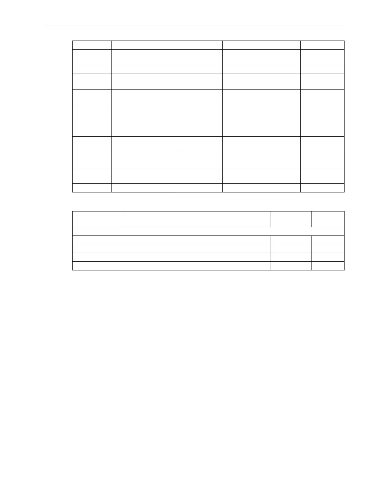
Addr. Parameter C Setting Options Default Setting
_:9721:103 Trigger f 1:Min. trigger
active
•
no
•
yes
yes
_:9721:104 Trigger f 1:Min. trigger 25.000 Hz to 50.000 Hz 49.600 Hz
_:9721:114 Trigger f 1:Min. trigger
hysteresis
1.001 p.u. to 1.010 p.u. 1.002 p.u.
_:9721:105 Trigger f 1:dM/dt rise
active
•
no
•
yes
no
_:9721:106 Trigger f 1:dM/dt rise (/
Filter time)
0.005 Hz to 60.000 Hz 0.100 Hz
_:9721:115 Trigger f 1:dM/dt rise
hysteresis
0.990 p.u. to 0.999 p.u. 0.998 p.u.
_:9721:107 Trigger f 1:dM/dt drop
active
•
no
•
yes
no
_:9721:108 Trigger f 1:dM/dt drop (/
Filter time)
0.005 Hz to 60.000 Hz 0.100 Hz
_:9721:116 Trigger f 1:dM/dt drop
hysteresis
0.990 p.u. to 0.999 p.u. 0.998 p.u.
_:9721:112 Trigger f 1:Filter time 2 cycles to 250 cycles 2 cycles
Information List
No. Information Data Class
(Type)
Type
Trigger f 1
_:9721:54 Trigger f 1:Inactive SPS O
_:9721:52 Trigger f 1:Behavior ENS O
_:9721:53 Trigger f 1:Health ENS O
_:9721:301 Trigger f 1:Trigger active SPS O
Power Trigger
Overview of Functions
Power triggers start for the group triggers with exceeding or dropping below the set limiting values (level and
gradient trigger) in the fast-scan and slow-scan recorders. It is triggered on active power, reactive power,
apparent power, and power swing.
Structure of the Function
The Power trigger function is found in the 3-phase voltage/current function group, which is connected with
a 3-phase voltage and a 3-phase current measuring point.
The structure of the Power trigger function is shown in the following figure:
7.5.3.6
7.5.4
7.5.4.1
7.5.4.2
Fault Recorder
7.5 Trigger Functions 3-Phase
SIPROTEC 5, Fault Recorder, Manual 335
C53000-G5040-C018-5, Edition 11.2017

 Loading...


