The device calculates the fault voltage (V
F
) with the formula:
VF = |VA+ VB + VC + Vph/VN • VN |, where Vph/VN forms the Matching ratio Vph / VN parameter.
The Matching ratio Vph / VN parameter takes into account the differing transformation ratios between
the residual voltage input and the phase-voltage inputs.
You can find more information in this respect in chapter 8.3.3.1 Overview of Functions ).
Delay failure indication
When the threshold value for the delay of the failure indication (parameter: Delay failure indication)
is exceeded, the indication Failure is generated.
Blocking the Function
The following blockings reset the picked up function completely:
•
Externally or internally via the binary input signal
>Block function
•
A protection pickup
The pickup signal of a protection function blocks the
Failure
indication.
Application and Setting Notes
Parameter: Threshold
•
Recommended setting value (_:3) Threshold = 25 V
The Threshold parameter is used to set the voltage which the device uses to recognize the calculated fault
voltage (V
F
) as a failure of the voltage sums. Siemens recommends using the default setting.
Parameter: Delay failure indication
•
Recommended setting value (_:6) Delay failure indication = 5.00 s
Set the Delay failure indication parameter so that overfunctions due to disturbing influences (such as
switching operations) are avoided. Siemens recommends using the default setting.
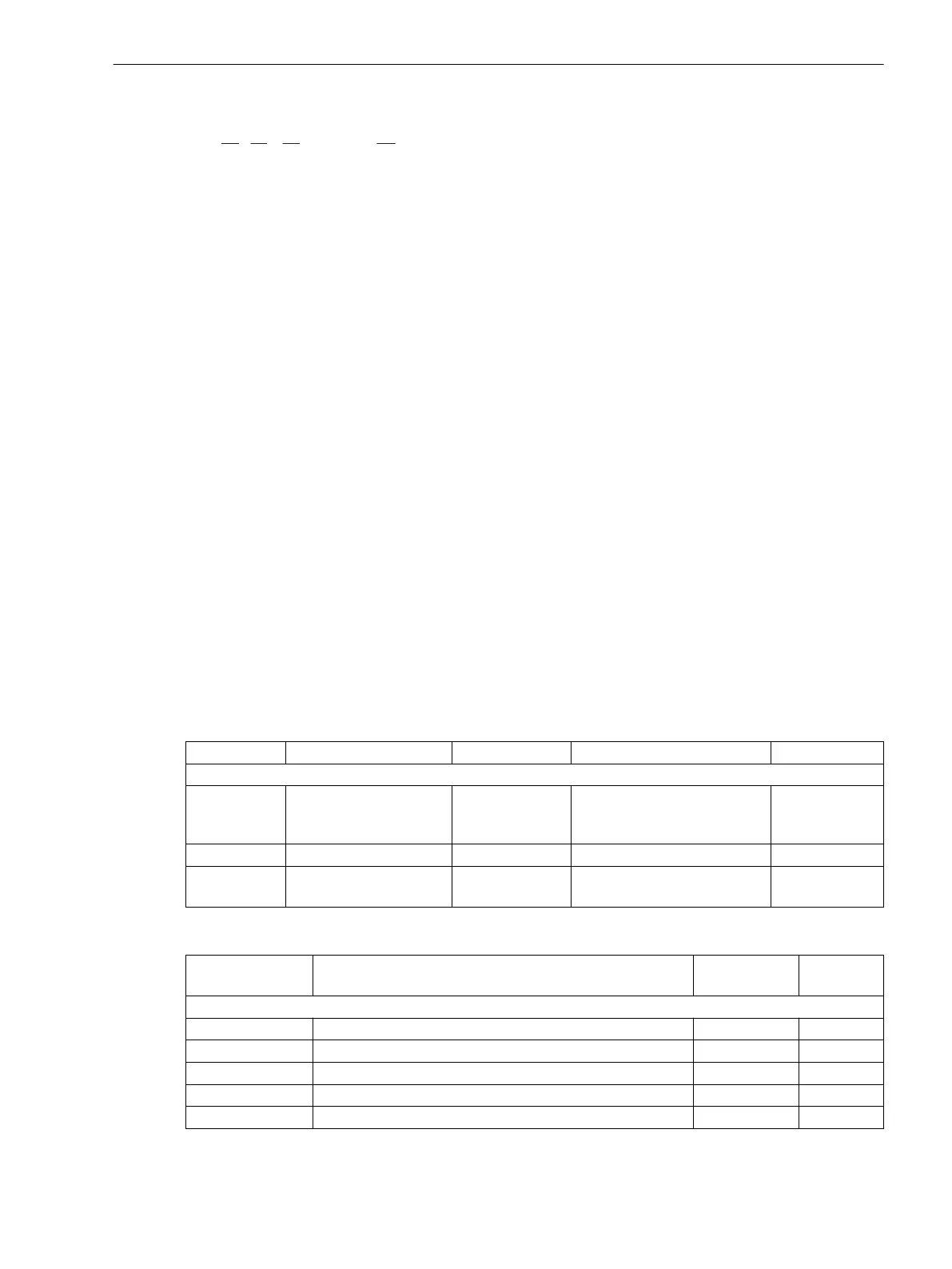
Settings
Addr.
Parameter C Setting Options Default Setting
Supv. sum V
_:1 Supv. sum V:Mode
•
off
•
on
•
test
off
_:3 Supv. sum V:Threshold 0.300 V to 170.000 V 43.300 V
_:6 Supv. sum V:Delay
failure indication
0.00 sto 100.00 s 5.00 s
Information List
No.
Information Data Class
(Type)
Type
Supv. sum V
_:82 Supv. sum V:>Block function SPS I
_:54 Supv. sum V:Inactive SPS O
_:52 Supv. sum V:Behavior ENS O
_:53 Supv. sum V:Health ENS O
_:71 Supv. sum V:Failure SPS O
8.3.3.4
8.3.3.5
8.3.3.6
Supervision Functions
8.3 Supervision of the Secondary System
SIPROTEC 5, Fault Recorder, Manual 377
C53000-G5040-C018-5, Edition 11.2017

 Loading...


