Resource-Consumption Supervision
Load Model
SIPROTEC 5 devices are freely configurable. A load model is integrated in DIGSI 5. The load model prevents you
from overloading the device with an excessively large application.
The load model shows the device utilization and the response times for device functions. If it determines that
an application created is likely to overload the device, DIGSI prevents the application from being loaded into
the device.
In this rare case, you must then reduce the application in order to be able to load it into the device.
The load model can be found in the DIGSI 5 project tree under Name of the device → Device information. In
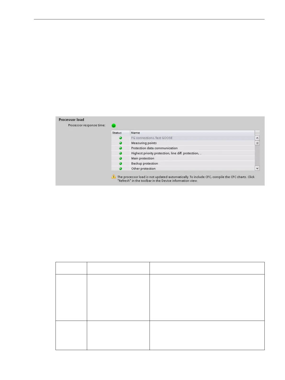
the operating range, select the Resource consumption setting sheet. The following figure shows an example
of the view of the load model in DIGSI 5:
[scressou_n, 1, en_US]
Figure 8-1 Visualization of the Load Model in DIGSI
A green total display for the processor response time indicates that the device is not overloaded by the present
application. On the other hand, if you see a red exclamation mark, the planned application is overloading the
device.
The list below the total display shows the individual functional areas. These areas combine functions with the
same real-time requirements in groups. A green display in front of an area (see Figure 8-1) indicates that the
response times of the functions grouped in this area can be maintained. A red exclamation point indicates that
functions may have longer response times than are specified in the Technical data for the device. In such a
case, loading of the application into the device is blocked.
The following table provides an overview of the functional areas and the most important influencing quanti-
ties on device utilization:
Functional
Area
Brief Description Change in Load
CFC event-trig-
gered, fast
CFC-charts, which must be
processed especially fast
Adding or removing CFC charts in the fast event-triggered
process range
•
Create CFC chart
•
Delete CFC chart
•
Change the process range in the properties of the CFC
chart
Add to or remove from CFC charts in the fast event-trig-
gered process area
Measuring
points
Provision of measured values
for measuring functions
Adding or removing
•
Measuring points (in the Measuring-points routing
Editor)
•
Function groups that provide measured-value prepro-
cessing for insertable functions
8.2
8.2.1
Supervision Functions
8.2 Resource-Consumption Supervision
SIPROTEC 5, Fault Recorder, Manual 363
C53000-G5040-C018-5, Edition 11.2017

 Loading...


