Parameter: Release threshold
•
Recommended setting value (_:101) Release threshold = 0.5 A for I
rated
= 1 A or 2.5 A for I
rated
= 5 A
The Release threshold parameter is used to set the lower limit of the maximum phase current (I
max
).
Parameter: Delay failure indication
•
Recommended setting value (_:6) Delay failure indication = 5.00 s
Set the Delay failure indication parameter so that overfunctions due to disturbing influences (such as
switching operations) are avoided.
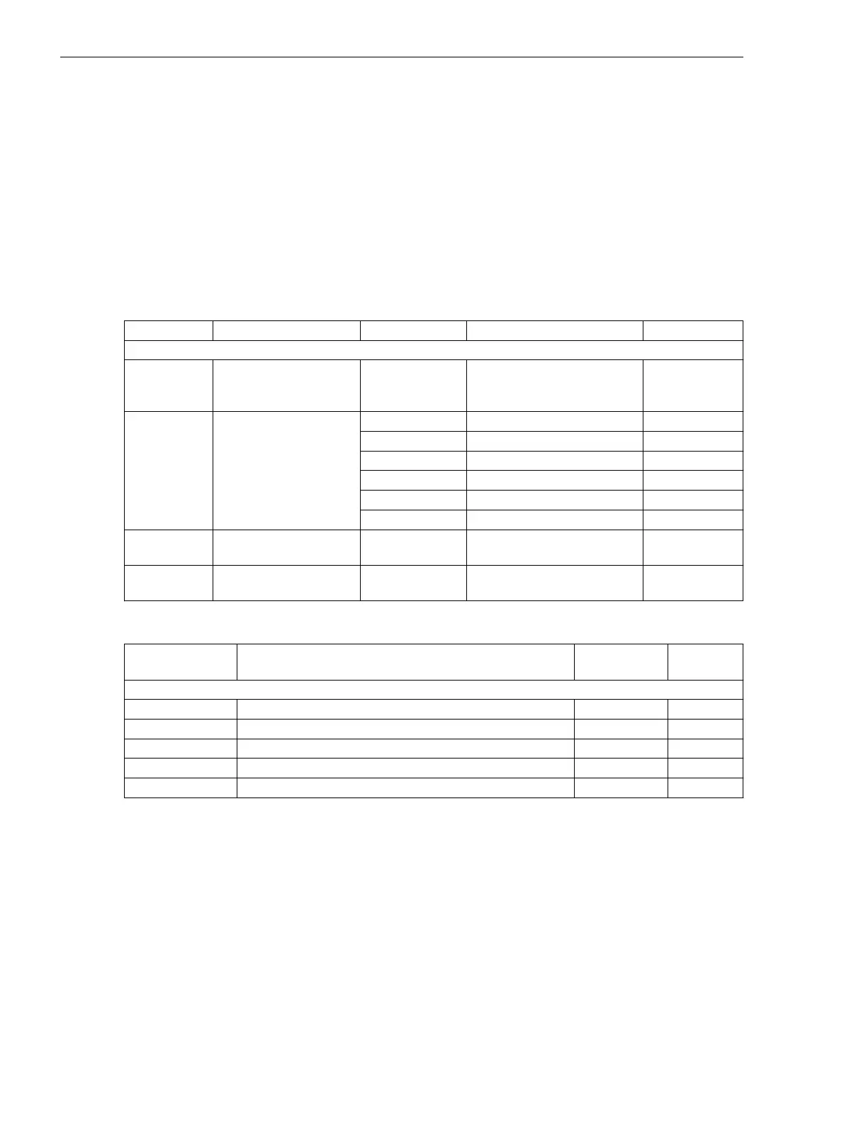
Settings
Addr. Parameter C Setting Options Default Setting
Supv. balan. I
_:1 Supv. balan. I:Mode
•
off
•
on
•
test
off
_:101 Supv. balan. I:Release
threshold
1 A @ 100 Irated 0.030 A to 35.000 A 0.500 A
5 A @ 100 Irated 0.15 A to 175.00 A 2.50 A
1 A @ 50 Irated 0.030 A to 35.000 A 0.500 A
5 A @ 50 Irated 0.15 A to 175.00 A 2.50 A
1 A @ 1.6 Irated 0.001 A to 1.600 A 0.500 A
5 A @ 1.6 Irated 0.005 A to 8.000 A 2.500 A
_:102 Supv. balan. I:Threshold
min/max
0.10 to 0.95 0.50
_:6 Supv. balan. I:Delay
failure indication
0.00 s to 100.00 s 5.00 s
Information List
No.
Information Data Class
(Type)
Type
Supv. balan. I
_:82 Supv. balan. I:>Block function SPS I
_:54 Supv. balan. I:Inactive SPS O
_:52 Supv. balan. I:Behavior ENS O
_:53 Supv. balan. I:Health ENS O
_:71 Supv. balan. I:Failure SPS O
Current-Sum Supervision
Overview of Functions
In healthy system operation, the sum of all currents at one measuring point must be approximately 0. The
Current-sum supervision function monitors the sum of all currents of one measuring point in the secondary
circuit. It detects connection errors during commissioning or short circuits and interruptions in the secondary
circuit.
For summation of the currents, the device requires the phase currents and the ground current of the current
transformer neutral point or of a separate ground-current transformer at this measuring point. Select the
following connection variant:
•
Current-transformer connections connected to 3 current transformers and the neutral point (see
Figure A-6 in the Attachment)
8.3.6.5
8.3.6.6
8.3.7
8.3.7.1
Supervision Functions
8.3 Supervision of the Secondary System
386 SIPROTEC 5, Fault Recorder, Manual
C53000-G5040-C018-5, Edition 11.2017

 Loading...


